
An equidistantly adjustable adhesive tape cutter fixing device

A fixing device and slitting knife technology, applied in the directions of transportation and packaging, thin material handling, and sending objects, can solve the problems of wasting more time, wasting manpower and time, and large production costs, saving labor and time, Convenient spacing adjustment and ingenious structure

Active Publication Date: 2019-04-19
芜湖徽氏新材料科技有限公司
View PDF6 Cites 0 Cited by
  • Summary
  • Abstract
  • Description
  • Claims
  • Application Information

AI Technical Summary

Problems solved by technology

[0003] When adjusting the spacing, due to the large number of slitting knives, it is necessary to adjust their positions before fixing them, which wastes a lot of manpower and time. At the same time, because this adjustment mainly depends on manual operation, the adjusted slitting knife spacing There will be errors, so that the width of the tape after slitting is uneven;
[0004] If the method of replacing the slitting knife fixture is adopted, since the size of the tape has various specifications, it is necessary to prepare various specifications of the fixture to ensure the smooth progress of production, which takes up a lot of production costs, and this replacement method will also waste more. It takes time to complete, which is not conducive to continuous production operations

Method used


Image

  • An equidistantly adjustable adhesive tape cutter fixing device
  • An equidistantly adjustable adhesive tape cutter fixing device
  • An equidistantly adjustable adhesive tape cutter fixing device

Examples


Embodiment Construction

[0017] The specific implementation manners of the present invention will be described in further detail below in conjunction with the accompanying drawings.

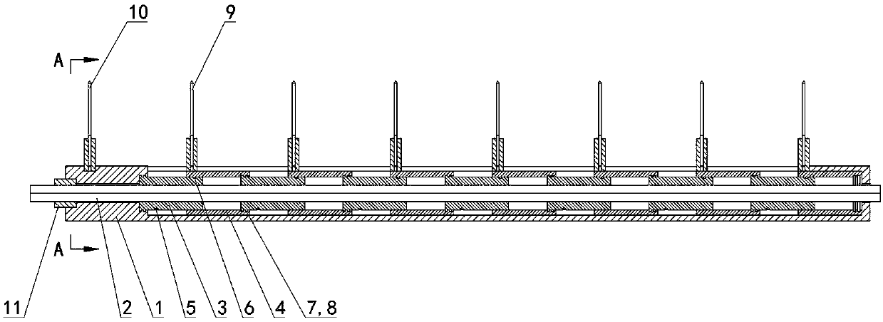
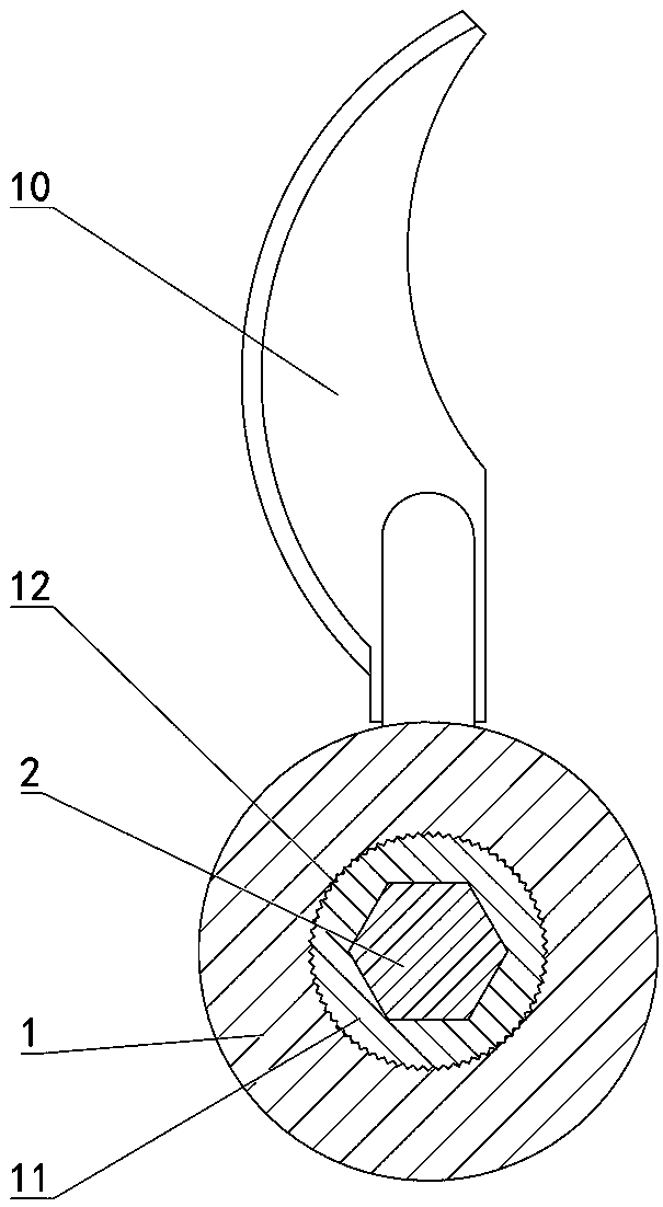
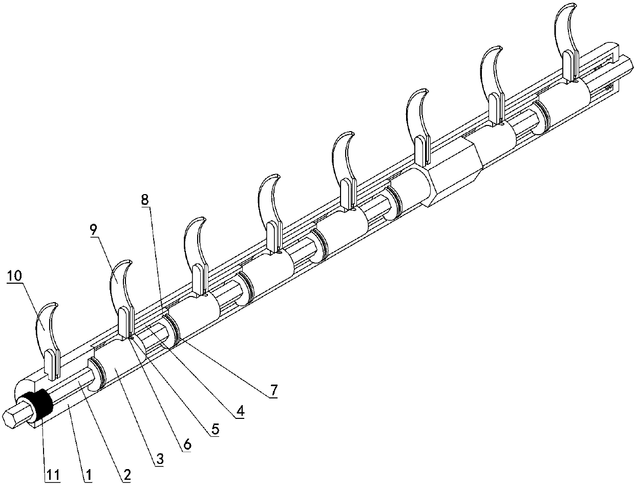
[0018] Depend on Figure 1 to Figure 6 Provide, the present invention comprises the fixed frame 1 that has the cylindrical cavity that is arranged horizontally, the rotatable rotating shaft 2 that coaxially arranges with the cavity is housed on the fixed frame 1, and a plurality of are placed in the cavity and sequentially arranged on the rotating shaft 2 Connected tool holder unit;

[0019] The tool holder unit includes a camshaft 3 coaxially arranged with the rotating shaft 2 and capable of sliding on the rotating shaft 2. The camshaft 3 is sleeved with a slide block 4 capable of sliding in the cavity. The outer edge of the camshaft 3 is provided with The spiral cam groove 5, the slider 4 is provided with a cam push rod 6 matching the cam groove 5, the cam push rod 6 is placed in the cam groove 5, and when the camshaf...


PUM


Abstract

The invention relates to an adhesive tape cutting knife fixing device capable of being adjusted at equal intervals. The adhesive tape cutting knife fixing device comprises a fixing frame with a horizontally-arranged cylindrical cavity body. The fixing frame is provided with a rotating shaft which is coaxially arranged with the cavity body. The rotating shaft is provided with a plurality of knife frame units which are placed in the cavity body. Each knife frame unit comprises a cam shaft which can slide on the rotating shaft. Each cam shaft is provided with a slidable sliding block in a sleeved mode. A spiral cam groove is formed in the outer edge surface of each cam shaft. Each sliding block is provided with a cam pushing rod matched with the corresponding cam groove. The cam pushing rods are placed in the cam grooves. The left ends of the cam shafts are provided with circumferential convex edges. Inner edge concave grooves which can be matched with circumferential convex edges are formed in the right ends of the sliding blocks. The cam shaft of any knife frame unit is connected with the sliding block of the adjacent knife frame unit at the left side through the corresponding circumferential convex edge and the corresponding inner edge concave groove. The circumferential convex edges are placed in the inner edge concave grooves. The cam shaft in any knife frame unit is rotationally connected with the fixing frame, or the sliding block in any knife frame unit is fixedly connected with the fixing frame. By means of the adhesive tape cutting knife fixing device capable of being adjusted at equal intervals, spacing adjustment of a cutting knife can be conveniently completed.

Description

technical field [0001] The invention relates to the technical field of tape processing and production equipment, in particular to an equidistantly adjustable tape cutting knife fixing device. Background technique [0002] In the tape processing and production process, after the tape raw material is processed, it needs to be rolled into a longer tape reel, and then it is slit or slit and re-rolled to obtain a product of a specified size; the tape reel is divided When cutting, in order to ensure the neat and uniform size, it is necessary to ensure that the distance between adjacent slitting knives remains consistent. When changing products or slitting into different sizes, it is necessary to adjust the spacing of the slitting knives or replace the slitting Knife mounting fixture. [0003] When adjusting the spacing, due to the large number of slitting knives, it is necessary to adjust their positions before fixing them, which wastes a lot of manpower and time. At the same tim...

Claims


Application Information

Patent Timeline
Patent Type & Authority Patents(China)
IPC IPC(8): B65H35/02
CPCB65H35/02
Inventor 李莉李峰李光富霍小军
Owner 芜湖徽氏新材料科技有限公司
Learn More