
Laser shock forming method and device for straight-wall cylindrical parts

A laser shock, cylindrical part technology, applied in the field of near-net-shape plastic processing of mechanical parts, can solve the problems of small inner circle diameter, restricted application promotion, irregular shock wave pressure field, etc., to achieve convenient position adjustment, safe and reliable operation , The effect of precise and controllable parameters

Active Publication Date: 2019-06-04
ANHUI UNIVERSITY OF TECHNOLOGY
View PDF5 Cites 0 Cited by
  • Summary
  • Abstract
  • Description
  • Claims
  • Application Information

AI Technical Summary

Problems solved by technology

This invention mainly solves the problem of cracking and failure in the forming process, but the ring-shaped spot will not only cause the optical path inside the laser to be extremely complicated, but also it is difficult to have a good coaxiality between the outer circle and the inner circle of the ring-shaped spot, so that the induced shock wave The irregular pressure field will lead to inconsistent deformation of the thin plate after being loaded, and the forming accuracy of the thin plate is poor
More importantly, limited by the output energy of the laser pulse, the inner diameter of the annular spot will be very small, and there is still a problem of forming accuracy in the forming process of a single solid spot in the impact forming process.
Therefore, the main problem of laser shock forming is the accuracy of thin plate forming. The existing technology cannot solve it well, which restricts the application and promotion of this technology.

Method used


Image

  • Laser shock forming method and device for straight-wall cylindrical parts
  • Laser shock forming method and device for straight-wall cylindrical parts
  • Laser shock forming method and device for straight-wall cylindrical parts

Examples


Embodiment

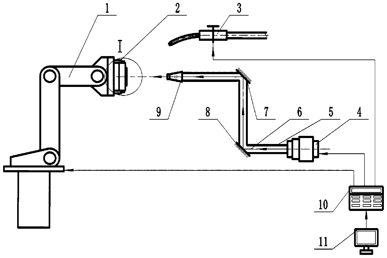
[0033] Embodiment: A flat-bottomed cylindrical cup of aluminum alloy Al2024-T315 is formed by using the method and device of the present invention.

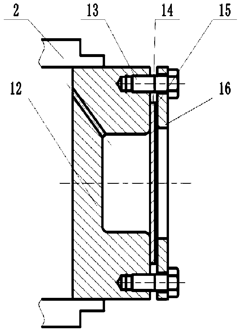
[0034] The size of the die is: the overall outer diameter of the die 12 is 20 mm, and the height is 2 mm; the cavity diameter is 4 mm, the depth is 0.8 mm, the side wall is straight, and the fillet radius of the top and bottom of the cavity is 0.3 mm. The thin metal plate 14 is a circular thin plate, the material of which is Al2024-T315, the thickness of the thin plate is 0.1 mm, and the diameter is φ20 mm. The forming process is as follows:

[0035] The circular sheet is placed directly above the cavity of the die 12 earlier. Coat a layer of black paint with a thickness of 0.1mm as the absorbing layer 15 on the central area of ​​the side of the circular thin plate to be impacted, and place a pressure plate 16. The middle part of the pressure plate 16 is provided with a middle hole with a diameter of φ4mm, and the bolt 13 is pas...


PUM

PropertyMeasurementUnit
diameteraaaaaaaaaa
thicknessaaaaaaaaaa
diameteraaaaaaaaaa

Abstract

The invention discloses a laser shock forming method and device for a straight-wall cylindrical part, and belongs to the field of plastic processing of near-net forming of metal parts. The method adopts a laser shock technology to carry out two-step forming on a thin plate so as to obtain a high-precision formed part and comprises the two steps that firstly, a laser with high pulse energy is used for inducing shock waves with high pressure to carry out impact on the thin plate so that the thin plate can be subjected to primary integral forming, but in the forming process, the thin plate is attached to the side wall of a die, in addition, the thin plate with extremely high deformation speed further collides with the bottom of a die cavity fiercely so that the bottom of the primary formed part can generate local reverse plastic deformation, and therefore the forming precision can be reduced; and secondly, a laser with low pulse energy is used for inducing shock waves with lower pressure to carry out impact on a reverse plastic deformation area at the bottom of the primary formed part so as to eliminate the reverse plastic deformation at the bottom of the primary formed part in the first step, and correction setting is carried out on the primary formed part so that the forming precision of the straight-wall cylindrical part can be greatly improved. According to the method, the laser shock forming precision of the thin plate can be greatly improved, and the method has wide practicability.

Description

Technical field: [0001] The invention belongs to the technical field of near-net-shaping plastic processing of mechanical parts, and in particular relates to a laser shock forming method and device for straight-wall cylindrical parts. The invention is particularly suitable for precision forming of tiny straight-wall components. Background technique: [0002] Laser shock forming technology is a sheet metal forming technology that uses laser-induced high-voltage shock waves. It has potential application values ​​in aerospace, automobiles, toys, electronics, micro-electro-mechanical systems and other fields, for example, the forming of micro-shaped components in micro-electro-mechanical systems . Due to the good controllability and repeatability of laser pulse parameters, laser shock forming technology has attracted more and more attention. [0003] According to whether a mold is used in sheet metal forming, laser shock forming can be divided into two types: model laser shock ...

Claims


Application Information

Patent Timeline
Patent Type & Authority Patents(China)
IPC IPC(8): B21D26/06B21D37/10
CPCB21D26/06B21D37/10
Inventor 张兴权纪啸天纪看看裴善报陈彬童靳于张义伟尹元德王会廷李胜祗
Owner ANHUI UNIVERSITY OF TECHNOLOGY
Learn More