
Radio-frequency switch circuit and method for processing radio-frequency signals

A technology of radio frequency signals and radio frequency switches, applied in the direction of electrical components, transmission systems, etc., can solve the problems of poor isolation, affecting signal transmission quality and transmission distance, and large signal loss, so as to improve harmonic problems, reduce loss, Effect of Suppressing Harmonic Components

Pending Publication Date: 2017-12-26
SHANGRUI MICROELECTRONICS SHANGHAI
View PDF10 Cites 3 Cited by
  • Summary
  • Abstract
  • Description
  • Claims
  • Application Information

AI Technical Summary

Problems solved by technology

[0004] However, with the increase of PA branch ports and the increase of operating frequency, the traditional RF switch circuit has a large signal loss during the transmission of RF signals, which affects the signal transmission quality and transmission distance; moreover, each of the traditional RF switch circuits Branch isolation becomes worse as the frequency of the RF signal increases

Method used


Image

  • Radio-frequency switch circuit and method for processing radio-frequency signals
  • Radio-frequency switch circuit and method for processing radio-frequency signals
  • Radio-frequency switch circuit and method for processing radio-frequency signals

Examples


Embodiment Construction

[0046] The present invention will be described in further detail below in conjunction with the examples.

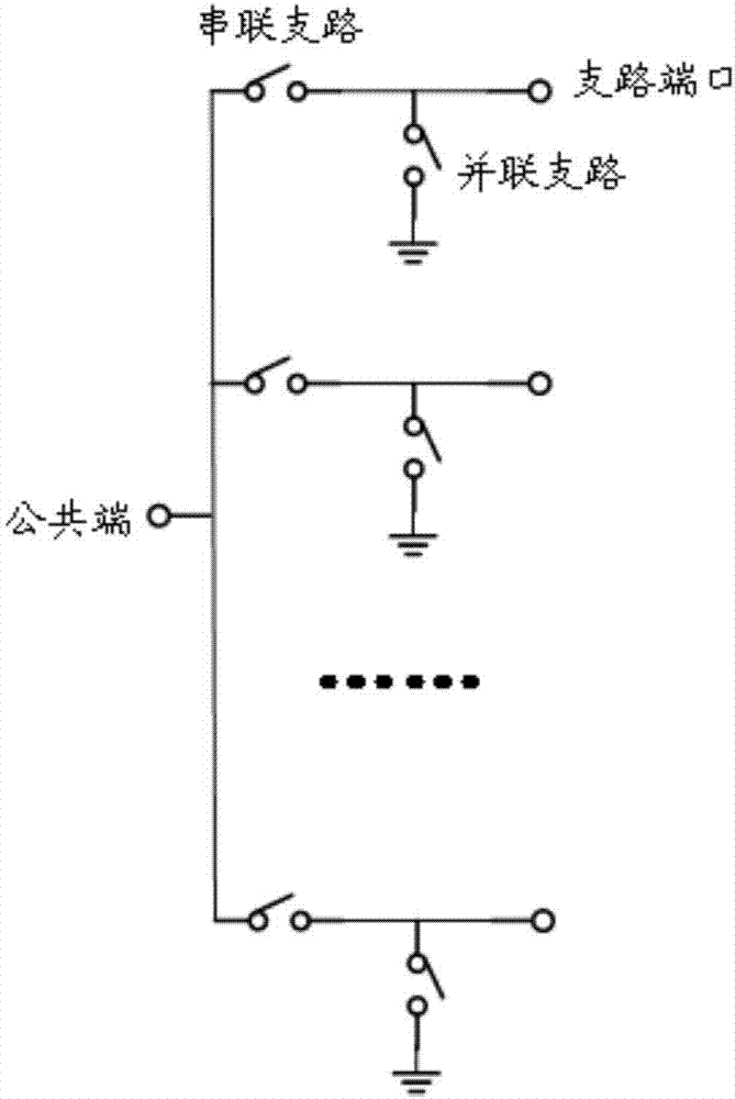
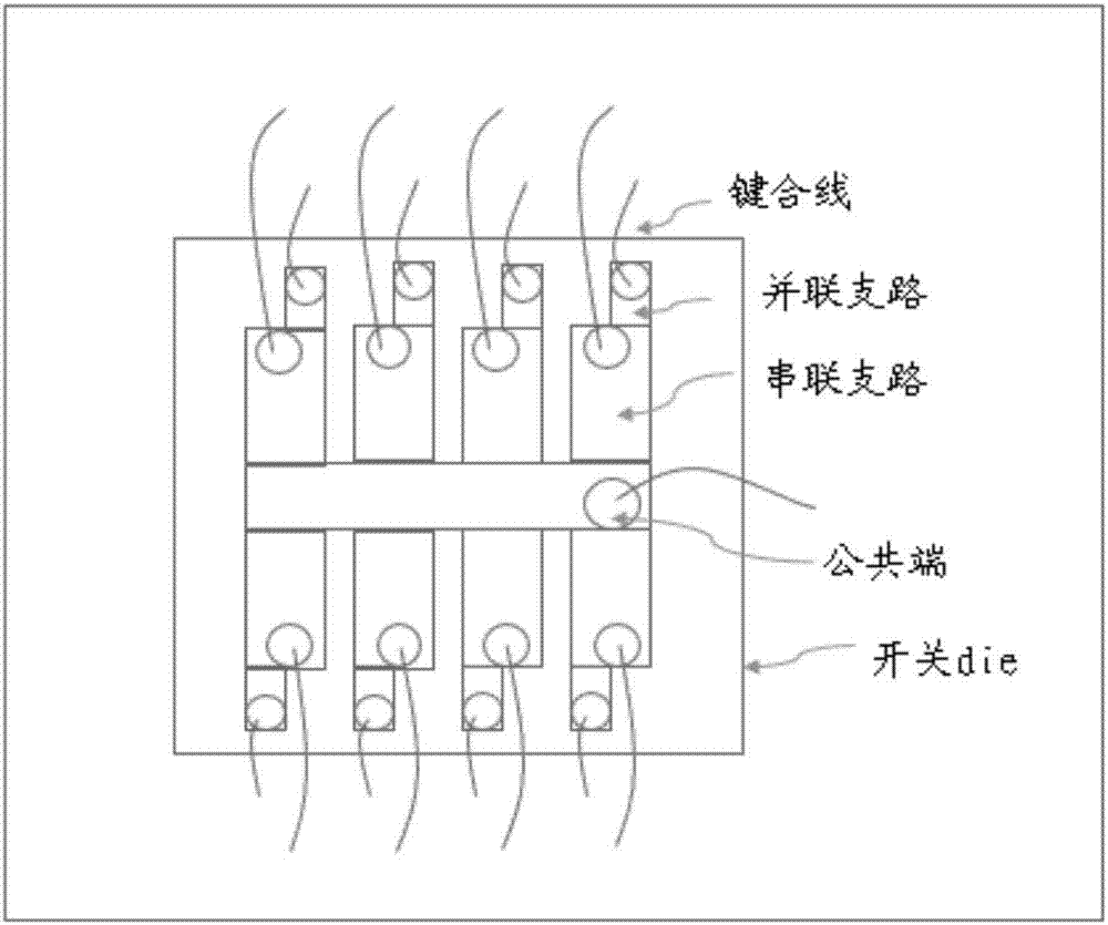
[0047] figure 2 is a schematic structural diagram of a traditional RF switch circuit; figure 2 As shown, the traditional RF switch circuit includes: a common terminal and at least two switch branches; the switch branch includes: a series branch and a parallel branch; the series branch is used to be guided The RF signal is transmitted in turn; the parallel branch is used to improve the isolation between the switch branches. However, in high-frequency application scenarios, the impedance of the switch in the parallel branch cannot be grounded well due to the inductive effect of the gold wire bonding (bondwire) and the parasitic effect of the switch itself, and the parallel branch cannot effectively guide the signal to the ground. It leads to the ground, which in turn leads to poor isolation between switching branches.

[0048] Here, the series branch and the parallel b...


PUM


Abstract

The invention discloses a radio-frequency switch circuit. The radio-frequency switch circuit comprises a common terminal and at least two switch branches, wherein the common terminal is used for receiving radio-frequency signals and inputting the radio-frequency signals into the switch branches corresponding to frequencies of the radio-frequency signals, and the switch branches are used for transmitting the radio-frequency signals during connection and suppressing harmonic components of the radio-frequency signals during transmission. The invention further discloses a method of the radio-frequency switch circuit for processing the radio-frequency signals.

Description

technical field [0001] The invention relates to mobile communication technology, in particular to a radio frequency (RF, Radio Frequency) switch circuit and a method for processing RF signals. Background technique [0002] With the development of mobile communication technology, from the second generation mobile communication technology (2G, 2-Generation wirelesstelephone technology), the third generation mobile communication technology (3G, 3rd-Generation), the long-term evolution of general mobile communication technology (LTE, Long Term Evolution) to the fifth-generation wireless broadband transmission technology (5G, 5th-Generation) and other communication protocols, there are more and more communication frequency bands, and the frequency span is also from 700MHz to 6GHz. It is expected that the upcoming 5G will have more than 100 frequency bands . Due to the large number of frequency bands and the large frequency span, the multi-mode multi-band (MMMB, Multi-Mode Multi-...

Claims


Application Information

Patent Timeline
IPC IPC(8): H04B1/00
CPCH04B1/005H04B1/006
Inventor 张巳龙彭洋洋陈泽岩
Owner SHANGRUI MICROELECTRONICS SHANGHAI
Learn More