
High-frequency earthquake area converter station slope settlement monitoring method based on InSAR technology

A subsidence monitoring and converter station technology, applied in height/horizontal measurement, measuring devices, surveying and navigation, etc., can solve time and space phase loss, PS point interference, inability to accurately obtain small changes in slopes and anti-slide piles and Settlement and other problems, to achieve stable position, strong radar signal reflection, and solve the effect of serious interference on permanent scatterers

Inactive Publication Date: 2017-12-26
DALI BUREAU OF ULTRA HIGH VOLTAGE TRANSMISSION CO CHINA SOUTHERN POWER GRID CO LTD
View PDF4 Cites 4 Cited by
  • Summary
  • Abstract
  • Description
  • Claims
  • Application Information

AI Technical Summary

Problems solved by technology

For the settlement monitoring of converter station (substation) slopes in high-altitude and high-frequency earthquake areas, since most areas of high slopes adopt ecological slope design, a large number of green plants that help slope stability are planted, but in Due to the dense vegetation on the radar image, the temporal-spatial loss of correlation in the InSAR observations is serious, that is, the PS point is seriously disturbed, which makes the InSAR technology unable to accurately obtain the small changes and settlements of the slope and anti-slide piles

Method used


Image

  • High-frequency earthquake area converter station slope settlement monitoring method based on InSAR technology
  • High-frequency earthquake area converter station slope settlement monitoring method based on InSAR technology
  • High-frequency earthquake area converter station slope settlement monitoring method based on InSAR technology

Examples


Embodiment

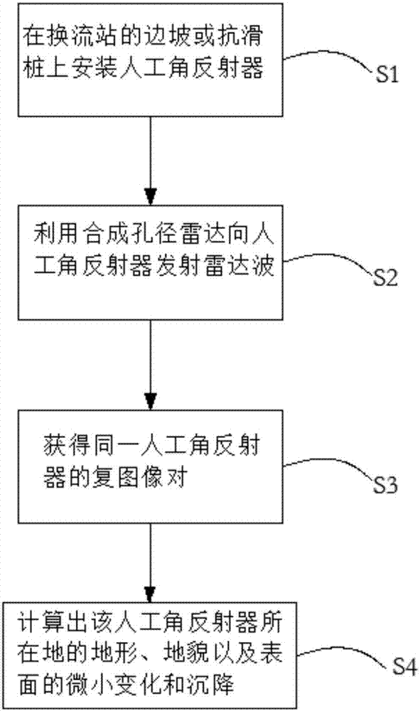
[0022] Please refer to figure 1 , a method for monitoring the slope settlement of a converter station in a high-frequency earthquake area based on InSAR technology, which includes the following steps:

[0023] (1) installing an artificial corner reflector on the slope or anti-slide pile of the converter station, and the artificial corner reflector is used as a permanent scatterer;

[0024] (2) Utilize synthetic aperture radar to transmit radar waves to artificial corner reflectors;

[0025] (3) obtaining the complex image pair of the same artificial corner reflector;

[0026] (4) Using the phase difference of the complex image pair of the artificial corner reflector, the path difference of the microwaves in the two imaging is obtained, and thus the topography, topography, and surface slight changes and settlements where the artificial corner reflector is located are calculated.

[0027] Such as figure 2 Shown is a schematic diagram of the geometry of the surface deformatio...


PUM


Abstract

The invention discloses a high-frequency earthquake area converter station slope settlement monitoring method based on an InSAR technology. The method comprises the following steps: (1) a manual corner reflector is arranged on the slope or an anti-slide pile of the converter station, wherein the manual corner reflector is used as a permanent scatterer; (2) a synthetic aperture radar is used to transmit radar waves to the manual corner reflector; (3) a complex image pair of the same manual corner reflector is acquired; and (4) by using the phase difference of the complex image pair of the manual corner reflector, a microwave path difference in twice imaging is obtained, and small changes and settlement of the topography, the geomorphology and the surface of the manual corner reflector are then calculated. The manual corner reflector is used to avoid dense vegetation interference, the problem that a high slope area converter station permanent scatterer point is severely disturbed can be solved, and the small changes and the settlement of the slope and the anti-slide pile are obtained accurately.

Description

technical field [0001] The invention relates to the field of terrain subsidence monitoring, in particular to a method for monitoring side slope subsidence of a converter station in a high-frequency earthquake area based on InSAR technology. Background technique [0002] The full name of InSAR technology is Spaceborne Synthetic Aperture Radar Interferometry. InSAR technology is a satellite geodesy method developed rapidly in the past forty years. Its main feature is to use the phase information in radar data to monitor surface displacement changes and extract ground deformation data. . Compared with traditional measurement methods, it has the advantages of wide coverage, high spatial resolution, all-day, all-weather, high precision, no need for ground control points, and no need for surveyors to enter the field. In recent years, it has been widely used to monitor various geological Surface deformation caused by disasters. [0003] InSAR technology obtains the surface deform...

Claims


Application Information

Patent Timeline
IPC IPC(8): G01S13/90G01C5/00G01C7/02
CPCG01C5/00G01C7/02G01S13/9023
Inventor 邱毅楠余荣兴陈超泉朱丹艾传鲜潘毅孔小敏彭永来刘可阳王勉刘宏明赵建明
Owner DALI BUREAU OF ULTRA HIGH VOLTAGE TRANSMISSION CO CHINA SOUTHERN POWER GRID CO LTD
Learn More