Energy-saving control method and system of microwave oven
A control method and technology for microwave ovens, applied in the field of microwave ovens, can solve the problems of high cost, low stability and safety, and large energy consumption, and achieve the effects of stable heating, food assurance, and precise control.
- Summary
- Abstract
- Description
- Claims
- Application Information
AI Technical Summary
Problems solved by technology
Method used
Image
Examples
Embodiment 1
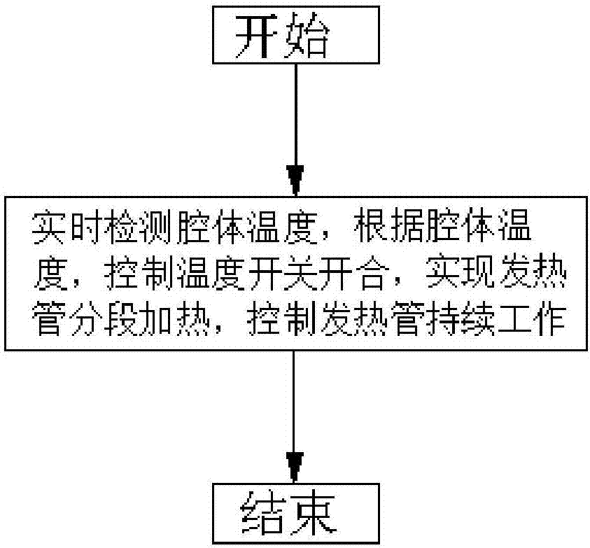
[0030] refer to figure 1 , an energy-saving control method for a microwave oven. When an instruction to start a microwave oven is received, the temperature of the cavity of the microwave oven is detected in real time; according to the temperature of the cavity, the opening and closing of different temperature switches are controlled, thereby realizing automatic segmental control and delivery to The power of the heating tube of the microwave oven is used to control the temperature of the cavity during the continuous operation of the heating tube until the temperature of the cavity reaches the predetermined temperature, and then the microwave oven is turned off to end the heating.
[0031] According to the temperature of the cavity, the steps of controlling the power delivered to the heating tube are as follows:
[0032] The cavity temperature is set to three temperature ranges, respectively 0-T1, T1-T2, T2-T3, each temperature range corresponds to a power heating tube, respecti...
Embodiment 2
[0035] refer to figure 2 , the temperature detection unit 101 is used to detect the cavity temperature of the microwave oven in real time when receiving the instruction to start the microwave oven, the temperature detection unit 101 is a temperature sensor, which is arranged on the cavity of the microwave oven, and is used to detect the cavity temperature signal, And pass this signal to the temperature switch S0, S1, S2. The control circuit 102 is connected to the temperature switch and the coil of the relay to control the heating of the heating tube in sections. The control circuit 102 is connected to the 12V power supply V, and the temperature switches S0, S1, and S2 are connected in parallel to the control circuit. At the same time, the temperature switches S0, S1, and S2 They are respectively connected in series with the relay coils KM1, KM2 and KM3, and the main circuit 103 is controlled by closing and disconnecting the relay coils KM1, KM2 and KM3, and the control is sa...
Embodiment 3
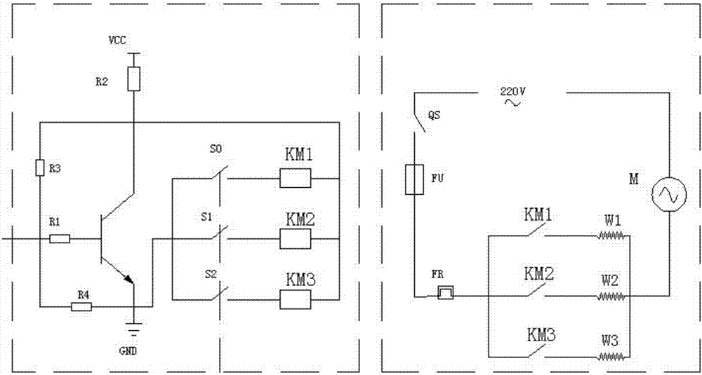
[0038] refer to image 3 , the electrical schematic diagram of the main circuit and the control circuit, the control circuit is connected to the 12V power supply V, the resistor R2 is connected in series, and then the collector of the transistor is connected in series, the emitter of the transistor is grounded to GND, the base is connected in series with the bias resistor R1, and at the same time , the temperature resistor S0 is connected in series with the relay coil KM1, the temperature resistor S1 is connected in series with the relay coil KM2, the temperature resistor S2 is connected in series with the relay coil KM3, and then connected in parallel to the circuit, connecting the emitter and the collector, and the collector and the base in parallel Resistor R3 and the left end of resistor R1 are connected in parallel to resistor R4 and connected to the emitter; the main circuit is connected to 220V AC power supply, and at the same time, the switch QS is connected to control ...
PUM
 Abstract
Description
Claims
Application Information
 - R&D
- Intellectual Property
- Life Sciences
- Materials
- Tech Scout
- Unparalleled Data Quality
- Higher Quality Content
- 60% Fewer Hallucinations
Browse by: Latest US Patents, China's latest patents, Technical Efficacy Thesaurus, Application Domain, Technology Topic, Popular Technical Reports.
© 2025 PatSnap. All rights reserved.Legal|Privacy policy|Modern Slavery Act Transparency Statement|Sitemap|About US| Contact US: help@patsnap.com


