
Stretchable breaking type PDC compound drill bit

A composite drill bit and drill bit technology, which is applied in the direction of drill bits, drilling equipment, earthwork drilling, etc., can solve the problems of thermal wear, increased PDC tooth wear speed, and high penetration difficulty, so as to ensure mechanical rigidity, avoid rapid wear, and increase connection area effect

Inactive Publication Date: 2017-12-22
弘毅天承知识产权股份有限公司
View PDF0 Cites 9 Cited by
  • Summary
  • Abstract
  • Description
  • Claims
  • Application Information

AI Technical Summary

Problems solved by technology

[0004] When the PDC bit drills in a hard formation, it is difficult for the PDC bit head to invade (eat) the rock surface at the bottom of the well, especially when the PDC teeth are worn to a certain extent, the invasion is more difficult, causing the bit to slip at the bottom of the well, and the drill extremely slow
Thereby, there are following technical problems in the prior art: 1, rely on pure shearing state to break the rock, the cutting teeth of the drill bit core are very low relative to the peripheral cutting teeth cutting linear velocity, which causes the PDC drill bit to slow down, seriously restricting the performance of the PDC drill bit. Rock-breaking efficiency; 2. PDC teeth continuously cut rocks, and the heat generated by intense friction will cause the teeth to reach a relatively high temperature. When the temperature exceeds the maximum thermal load, the wear rate of PDC teeth will increase significantly, resulting in thermal wear. happened
3. The wear rate of the PDC teeth on different radial areas of the drill bit is significantly different. Generally, the wear rate of the cutting teeth in the outer area of ​​the drill bit (especially the outer 1 / 3 area of ​​​​the drill bit radius) is significantly faster than that of the cutting teeth in the core area. After wear The drill bit needs to be replaced as a whole, and the cost is high

Method used


Image

  • Stretchable breaking type PDC compound drill bit
  • Stretchable breaking type PDC compound drill bit

Examples


Embodiment Construction

[0027] The implementation of the present invention will be illustrated by specific specific examples below, and those skilled in the art can easily understand other advantages and effects of the present invention from the contents disclosed in this specification.

[0028] The present invention will be described in further detail below by means of specific embodiments:

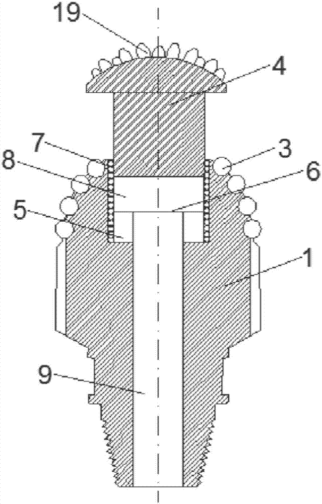
[0029] Such as figure 1 As shown, the present embodiment provides a retractable broken PDC composite drill bit, including a drill body 1 and a blade 2 integrally formed with the drill body 1, the blade 2 includes a main blade 16 and an auxiliary blade 17, the main blade 16 and The secondary blades 17 are fixed on the bit body 1 in the form of an Archimedes spiral, the main blade 16 and the secondary blade 17 are provided with several drill bit cutting teeth 3, and the main blade 16 and the secondary blade 17 are provided with The drill bit cutting teeth 3 on the main cutter wing 16 and the auxiliary cutter win...


PUM

PropertyMeasurementUnit
Melting pointaaaaaaaaaa
Thicknessaaaaaaaaaa

Abstract

The invention provides a retractable and broken PDC composite drill bit, which relates to the technical field of oil drilling tools, and includes a drill body and a blade fixed on the drill body. The blade is provided with several cutting teeth. The drill bit The center of the body is provided with a breaker bit detachably connected to the drill body, an embedding groove for inserting the breaker bit, and an ejection mechanism, and the ejection mechanism is arranged in the drill body and is fixedly connected with the breaker bit; the drill body A floating support block is arranged between the broken drill bit. Through the implementation of this technical solution, the rock-breaking efficiency of the core of the drill bit can be effectively improved, and the technical problem that the PDC bit is difficult to drill in the hard formation is overcome; and the drill bit body around the broken bit body will not be caused faster Wear and tear is conducive to improving the service life of the drill bit and saving drilling costs.

Description

technical field [0001] The invention relates to the technical field of oil drilling tools, in particular to a retractable broken PDC composite drill bit. Background technique [0002] The drill bit is a rock-breaking tool used in drilling engineering to break rock and form a wellbore. Conventional drill bits used in today's drilling engineering mainly include three-cone drill bits, polycrystalline diamond compact drill bits (ie PDC drill bits) and rotary drill bits (also known as rotary punch drill bits or drill bits). [0003] The PDC drill bit is a kind of drill bit that uses the polycrystalline diamond composite sheet (ie PDC tooth) to scrape or shear the rock to break the rock. Due to the outstanding advantages in the performance of cutting elements and rock-breaking methods, the rock-breaking efficiency of PDC bits in soft to medium-hard formations is significantly higher than that of tricone bits. Nowadays, PDC bits are used more and more in drilling engineering, and...

Claims


Application Information

Patent Timeline
IPC IPC(8): E21B10/43E21B10/54E21B10/62
CPCE21B10/43E21B10/54E21B10/62
Inventor 赵红昌陈伊苒
Owner 弘毅天承知识产权股份有限公司
Learn More