
Self-vibrating flow-jetting and grouting anchor rod integrated construction equipment and method

A technology of grouting bolts and construction equipment, which is applied in mining equipment, installation of bolts, earthwork drilling and mining, etc. It can solve the problems of high degree of rock fragmentation, short self-stabilization time of surrounding rock, and low drilling efficiency, and achieves the best results Good, cost-effective, good grouting quality and effect

Pending Publication Date: 2017-12-15
BINZHOU UNIV
View PDF3 Cites 9 Cited by
  • Summary
  • Abstract
  • Description
  • Claims
  • Application Information

AI Technical Summary

Problems solved by technology

[0008] The purpose of the present invention is to overcome the deficiencies of existing grouting bolts, provide a self-vibrating jet grouting bolt integrated construction equipment, and solve the problems of high rock fragmentation, crack development, and short self-stabilization time of surrounding rock in underground engineering. protection problems, as well as the low drilling efficiency, long construction period and complicated procedures caused by the hard rock at the bottom of the hole, it can be used as both permanent support and temporary support

Method used


Image

  • Self-vibrating flow-jetting and grouting anchor rod integrated construction equipment and method
  • Self-vibrating flow-jetting and grouting anchor rod integrated construction equipment and method
  • Self-vibrating flow-jetting and grouting anchor rod integrated construction equipment and method

Examples


Embodiment Construction

[0028] The present invention provides an integrated construction equipment for self-vibrating jet grouting and bolting. In order to make the purpose, technical solution and effect of the present invention clearer and clearer, the specific implementation of the present invention will be described in detail below in conjunction with the accompanying drawings.

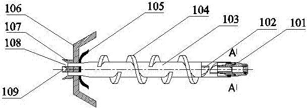
[0029] Such as Figure 1 to Figure 6 As shown, the self-vibrating jet grouting bolt integrated construction equipment of the present invention includes a self-vibrating jet grouting bolt 1, a high-pressure rotary grouting mixer 2, a grouting device, and a hydraulic drive device.

[0030] In the self-vibrating jet grouting bolt 1, a self-vibration generator 102 is installed at the front end of the bolt, and the self-vibration generator 102 is connected to the drill bit 101 to form an axial vibration impact so as to efficiently drill rocks. The bolt body 103 The rear end is provided with a grout stopper 105, a tray 106, a g...


PUM


Abstract

The invention discloses self-vibrating flow-jetting and grouting anchor rod integrated construction equipment and method. The equipment is composed of a self-vibrating flow-jetting and grouting anchor rod, a high-pressure rotary slurry mixing device, a grouting device and a hydraulic driving device. The self-vibrating flow-jetting and grouting anchor rod is a hollow rod body with a screw-edge stirring piece, and the front end of the anchor rod is provided with a vibration generator which is connected with a drill bit; the upper portion of the high-pressure rotary slurry mixing device is provided with a feed hole, the bottom of the high-pressure rotary slurry mixing device is provided with a rotary supporting leg which can freely lift and rotate, the front portion of the high-pressure rotary slurry mixing device is provided with a flow-jetting spray pipe, an inner cavity is provided with a rotating shaft, the front end of the rotating shaft is provided with a connection plug, the connection plug is cooperated and connected with a connection inserted groove of the self-vibrating flow-jetting and grouting anchor rod, the rear end of the rotating shaft is provided with a bearing, and the two ends of the rotating shaft are provided with high-pressure sealing boxes. The grouting device adjusts the grouting amount and the grouting pressure at any time, and the hydraulic driving device provides rotating power. The equipment and the method is widely used in support and reinforcement engineering in mines, transportation, water conservancy and other engineering fields, the application prospect is broad and the economic benefit is remarkable.

Description

technical field [0001] The invention relates to bolts used in the fields of mining, transportation, water conservancy and engineering. Background technique [0002] In the fields of mining engineering, geotechnical engineering, tunnel engineering, etc., in order to prevent the deformation or instability of the formation and surrounding rock and endanger the safety of the project, it is necessary to support and strengthen the surrounding rock of the formation, and the bolt support reinforcement technology is the most widely used a support technology. Bolt support can not only give full play to the stability of the rock and soil itself, but also has little disturbance to the original rock, fast construction speed, safe and reliable, and economical and effective. Therefore, it is used in mine support, tunnel support, slope support, large-scale It is widely used in the support of underground chambers, as well as anti-floating and anti-overturning projects of various buildings. ...

Claims


Application Information

Patent Timeline
IPC IPC(8): E21D20/02
CPCE21D20/02
Inventor 邢雪阳朱庆文
Owner BINZHOU UNIV
Learn More