Vertical-horizontal combined film evaporator

A thin-film evaporator and combined technology, which is applied in the field of vertical-horizontal combined thin-film evaporators, can solve problems such as fast flow rate, failure to meet drying requirements, and insufficient treatment concentration, etc., to achieve continuous process, minimized losses, and high energy efficiency The effect of using

Pending Publication Date: 2017-12-19
QINGDAO UNIV OF SCI & TECH +1
View PDF6 Cites 4 Cited by
  • Summary
  • Abstract
  • Description
  • Claims
  • Application Information

AI Technical Summary

Problems solved by technology

[0003] Thin-film evaporators in the prior art include vertical thin-film evaporators and horizontal thin-film evaporators. In the vertical thin-film evaporator, the liquid material can form a uniform film on the evaporation surface under the action of the rotor, and most of the material is evaporated. The light component comes out, but the flow rate of the material in the evaporation cylinder is fast, so that the concentrated solid product contains a certain amount of wet component, which cannot meet the higher drying requirements
The horizontal thin film evaporator has a good effect on drying solid materials with high viscosity and certain moisture content. The dryness of the product can be controlled by controlling the residence time of the material in the evaporation cylinder, but the horizontal thin film evaporator has a relatively low treatment concentration. Thin, less viscous solutions do not achieve the desired results

Method used


Image

  • Vertical-horizontal combined film evaporator
  • Vertical-horizontal combined film evaporator
  • Vertical-horizontal combined film evaporator

Examples


Embodiment Construction

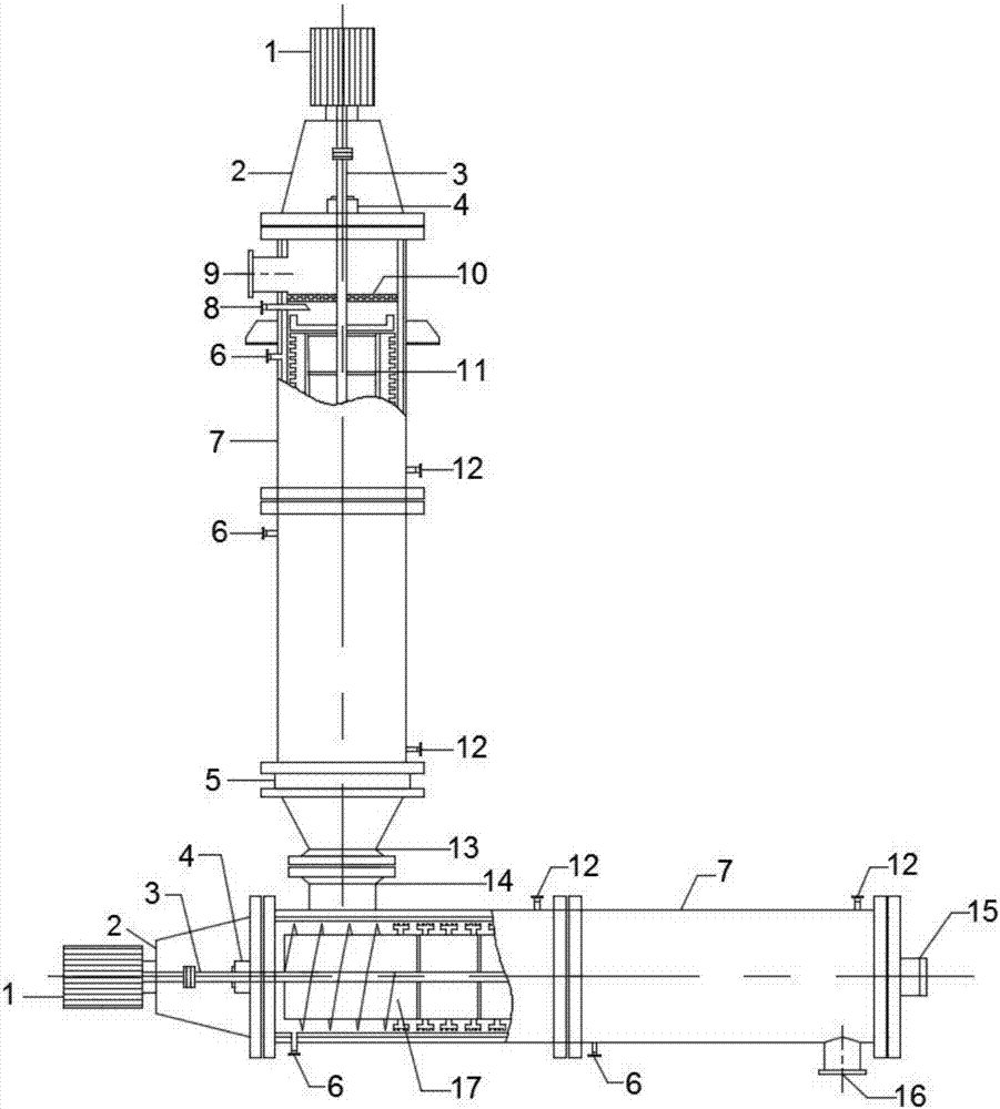
[0022] The following will clearly and completely describe the technical solutions in the embodiments of the present invention with reference to the drawings in the embodiments of the present invention. Such as figure 1 As shown, the present invention provides a vertical and horizontal combined thin film evaporator, including a vertical thin film evaporator, a horizontal thin film evaporator, a discharge port 13 of the vertical thin film evaporator and a feed port 14 of the horizontal thin film evaporator Connected by flange bolts; vertical thin film evaporator includes motor 1, reducer 2, main shaft 3, cylinder 7, rotor 11, foam capture and separation device 10, bottom bearing 5, horizontal thin film evaporator includes motor 1, reducer 2. Main shaft 3, barrel 7, rotor 17, end bearing 15; motor 1 is connected to reducer 2, reducer 2 is directly connected to main shaft 3 through a key, and mechanical seal 4 is used between main shaft 3 and barrel 7; The rotor 17 is rigidly con...


PUM


Abstract

The invention discloses a vertical-horizontal combined film evaporator which comprises a vertical film evaporator and a horizontal film evaporator, wherein a discharge hole of the vertical film evaporator is connected with a feed hole of the horizontal film evaporator through a flange bolt; the vertical film evaporator comprises a motor, a reducer, a spindle, a cylinder, a rotor, a foam catching device and a bottom bearing; the horizontal film evaporator comprises a motor, a reducer, a spindle, a cylinder, a rotor and an end bearing; the motor is connected with the reducer; the reducer is directly connected onto the spindle through a key; a mechanical seal is adopted between the spindle and the cylinder; the rotor is rigidly connected with the spindle in the cylinder; and two ends of the spindle are supported on two end faces of the cylinder. The vertical-horizontal combined film evaporator disclosed by the invention is compact in structure, reasonable in design and uniform in film distribution, and the retention time of materials in equipment can be well controlled, so that the product drying degree is controlled, the materials difficultly produce coking scales in the equipment, and the process requirements of removing volatile components and concentrating and drying the product in liquid feeding and solid discharging materials can be met. The vertical-horizontal combined film evaporator can be widely applied to the industries such as chemical industry, foods, medicines and the like.

Description

technical field [0001] The invention relates to the field of evaporators, in particular to a vertical and horizontal combined thin film evaporator. Background technique [0002] The thin-film evaporator is a high-efficiency evaporator that forms a film forcibly through a rotating scraper, and evaporates and concentrates under vacuum conditions. It has a large heat transfer coefficient, high evaporation intensity, and large operating flexibility. It is suitable for suspensions and pastes. The concentration, distillation and drying of materials are suitable for the concentration of heat-sensitive products, and are widely used in the fields of chemical industry, food and medicine. [0003] Thin-film evaporators in the prior art include vertical thin-film evaporators and horizontal thin-film evaporators. In the vertical thin-film evaporator, the liquid material can form a uniform film on the evaporation surface under the action of the rotor, and most of the material is evaporate...

Claims


Application Information

Patent Timeline
Patent Type & Authority Applications(China)
IPC IPC(8): B01D1/22B01D1/24
CPCB01D1/22B01D1/24
Inventor 段振亚王臣蒋文才刘茂睿
Owner QINGDAO UNIV OF SCI & TECH
Why Eureka
Try Eureka