Shielding cover, circuit board assembly, and electronic equipment
A circuit board assembly and shielding cover technology, applied in the directions of printed circuit components, printed circuits, electrical components, etc., can solve the problems of large impedance, affecting the effect of shielding radiation interference signals, and long loops, so as to reduce impedance and improve shielding. Effects of the ability to radiate interfering signals
- Summary
- Abstract
- Description
- Claims
- Application Information
AI Technical Summary
Problems solved by technology
Method used
Image
Examples
Embodiment 1
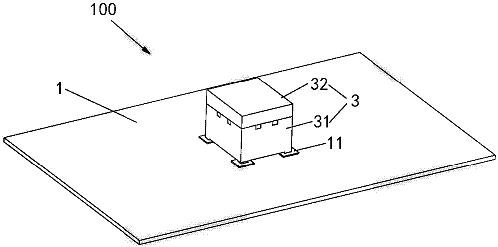
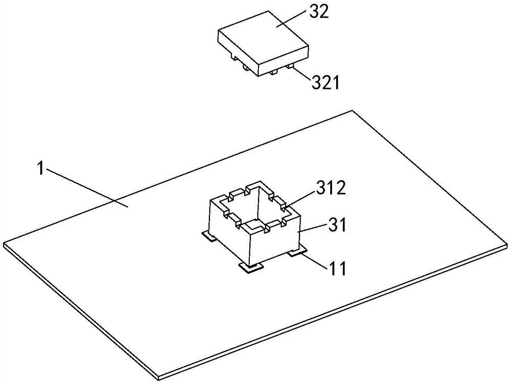
[0027] See Figure 1 to Figure 4 , this embodiment provides a circuit board assembly 100 , including a substrate 1 , an electronic module 2 and a shielding case 3 .
[0028] The electronic module 2 is disposed on the surface of the substrate 1 , and the shielding case 3 covers the electronic module 2 . The interior of the substrate 1 has a conductive layer 10 used as a reference ground, and at the same time, a positioning pad 11 is arranged on the surface of the substrate 1, and a jack 12 is opened in the area corresponding to the positioning pad 11, and the hole of the jack 12 There is a conductive element 13 on the wall. In this embodiment, the conductive element 13 is a copper sheet covering the wall of the insertion hole 12 . The conductive element 13 is in contact with the conductive layer 11 to realize electrical connection.
[0029] The shielding case 3 includes a shielding frame 31 and a shielding cover 32. The shielding cover 32 is set on the top of the shielding fra...
Embodiment 2
[0035] The difference between this embodiment and the first embodiment lies in that the positions of the concave-convex structures in this embodiment are changed. See Figure 6 , the edge of the bottom surface of the shielding cover 32 extends out of the side wall 322 protruding from the bottom surface, the inner side of the side wall 322 is provided with a second boss 323, and correspondingly, the outer side of the top of the shielding frame 31 is provided with a second groove 313, The second protrusion 323 of the shielding cover 32 is fitted into the second groove 313 of the shielding frame 31 .
[0036] It is easy to understand that the positions of the above-mentioned second boss 323 and the second groove 313 can be reversed. See Figure 7 , is another structure of the shield provided in this embodiment. The edge of the bottom surface of the shielding cover 32 extends out of the side wall 322 protruding from the bottom surface, and the inner surface of the side wall 322...
Embodiment 3
[0039] The difference between this embodiment and Embodiment 1 is that this embodiment adds the structure of Embodiment 2 on the basis of Embodiment 1. Please refer to Figure 8, the bottom surface of the shielding cover 32 is provided with a first boss 321 , the edge of the bottom surface of the shielding cover 32 extends from the side wall 322 protruding from the bottom surface, and the inner surface of the side wall 322 is provided with a second groove 324 . The top surface of the shielding frame 31 is provided with a first groove 312 , and at the same time, the outer surface of the top of the shielding frame 31 is provided with a second boss 314 . After the shielding cover 32 is combined with the shielding frame body 31, the first boss 321 of the shielding cover 32 is embedded in the first groove 312 of the shielding frame body 31, and the second boss 314 of the shielding frame body 31 is embedded in the first groove 314 of the shielding cover 32. Inside the two grooves 32...
PUM
 Abstract
Description
Claims
Application Information
 - Generate Ideas
- Intellectual Property
- Life Sciences
- Materials
- Tech Scout
- Unparalleled Data Quality
- Higher Quality Content
- 60% Fewer Hallucinations
Browse by: Latest US Patents, China's latest patents, Technical Efficacy Thesaurus, Application Domain, Technology Topic, Popular Technical Reports.
© 2025 PatSnap. All rights reserved.Legal|Privacy policy|Modern Slavery Act Transparency Statement|Sitemap|About US| Contact US: help@patsnap.com


