


Quick Research
Generate reliable direction feasibility study reports for your R&D in just a few steps.

Technical Q&A
Discover and master advanced knowledge NOW. Basics, ideas, possibilities, all at once.

Find Solutions
As an expert in R&D theories, this can generate solutions to your technical problems instantly.

Evaluate Feasibility
Analyze your overall solution with one click, know your potential R&D risks in advance.

Monitor Landscape
Get weekly tech updates, stay abreast of the latest tech innovations and key insights.
Plasma sheath curvature measurement method of ion thruster
An ion thruster and plasma technology, applied in the directions of plasma and electrical components, can solve the problem of not considering the curvature of the plasma sheath, and achieve the effect of ensuring measurement accuracy
- Summary
- Abstract
- Description
- Claims
- Application Information
AI Technical Summary
Problems solved by technology
Method used
Image

Examples
Embodiment Construction
[0021] The present invention will be described in detail below with reference to the accompanying drawings and examples.
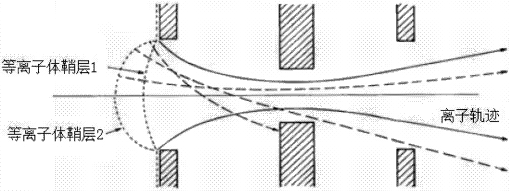
[0022] The invention provides a method for measuring the curvature of the plasma sheath of an ion thruster. The basic principle is to measure the plasma density based on the fact that the plasma density on the curved surface of the sheath is everywhere equal and the plasma density at the downstream adjacent position changes abruptly, so as to find out Sheath surface, and get the sheath curvature.
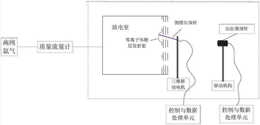
[0023] Such as figure 2 Shown is the plasma sheath curved surface measuring device of the present invention. The measuring device consists of a gas supply device, a mass flow meter, a Langmuir probe, a Faraday probe, a three-dimensional precision moving motor, and a control and data processing unit.
[0024] The measurement implementation steps are as follows:
[0025] Step 1. Change the gas flow rate of the high-purity xenon gas provided externally and dete...
PUM
 Abstract
Description
Claims
Application Information
 - R&D Engineer
- R&D Manager
- IP Professional
- Industry Leading Data Capabilities
- Powerful AI technology
- Patent DNA Extraction
Browse by: Latest US Patents, China's latest patents, Technical Efficacy Thesaurus, Application Domain, Technology Topic, Popular Technical Reports.
© 2024 PatSnap. All rights reserved.Legal|Privacy policy|Modern Slavery Act Transparency Statement|Sitemap|About US| Contact US: help@patsnap.com