


Quick Research
Generate reliable direction feasibility study reports for your R&D in just a few steps.

Technical Q&A
Discover and master advanced knowledge NOW. Basics, ideas, possibilities, all at once.

Find Solutions
As an expert in R&D theories, this can generate solutions to your technical problems instantly.

Evaluate Feasibility
Analyze your overall solution with one click, know your potential R&D risks in advance.

Monitor Landscape
Get weekly tech updates, stay abreast of the latest tech innovations and key insights.
RDS receiving method and apparatus
A receiving method and unreceived technology, which is applied in the field of RDS receiving method and device, can solve problems such as untimely terminal response and poor RDS command transmission effect, and achieve good broadcast effect, stable operation, and efficient broadcast effect
- Summary
- Abstract
- Description
- Claims
- Application Information
AI Technical Summary
Problems solved by technology
Method used
Image

Examples
Embodiment 1
[0026] According to an embodiment of the present invention, an embodiment of an RDS receiving method is provided. It should be noted that the steps shown in the flowchart of the accompanying drawings can be executed in a computer system such as a set of computer executable instructions, and, Although a logical sequence is shown in the flowchart, in some cases, the steps shown or described may be performed in a different order than here.
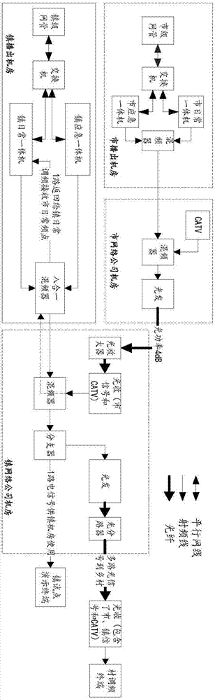
[0027] It should be noted that the RDS receiving method provided in the embodiment of the present invention is a method based on wired frequency modulation networking. The following will combine figure 2 A brief introduction to the structure of wired FM networking.
[0028] figure 1 It is a schematic diagram of a wired FM networking according to an embodiment of the present invention. The figure is a schematic diagram of city-town level networking.
[0029] From figure 1 It can be seen in figure 1 The all-in-one machine shown in is an FM modulato...
Embodiment 2
[0116] The embodiment of the present invention also provides an RDS receiving device. The RDS receiving device is mainly used to execute the RDS receiving method provided in the above content of the embodiment of the present invention. The following is a detailed description of the RDS receiving device provided by the embodiment of the present invention. Introduction.
[0117] Image 6 Is a schematic diagram of an RDS receiving device according to an embodiment of the present invention, such as Image 6 As shown, the RDS receiving device mainly includes: a first acquiring unit 61, a first judging unit 62, an adding unit 63, a polling unit 64 and a detecting unit 65, among which:
[0118] The first obtaining unit 61 is configured to obtain a message queue, and the message queue includes messages sent at at least one frequency point;
[0119] The first determining unit 62 is configured to determine, based on the message, whether a heartbeat instruction of the target main frequency is...
PUM
 Abstract
Description
Claims
Application Information
 - R&D Engineer
- R&D Manager
- IP Professional
- Industry Leading Data Capabilities
- Powerful AI technology
- Patent DNA Extraction
Browse by: Latest US Patents, China's latest patents, Technical Efficacy Thesaurus, Application Domain, Technology Topic, Popular Technical Reports.
© 2024 PatSnap. All rights reserved.Legal|Privacy policy|Modern Slavery Act Transparency Statement|Sitemap|About US| Contact US: help@patsnap.com