Steel-concrete combined continuous beam bridge for releasing pulling stress of carriageway slab

A bridge slab and tensile stress technology, which is applied in bridges, bridge parts, bridge construction, etc., can solve the problems of bridge slab structure complexity and difficulty in reaching the ideal level, and achieve simplified structure and construction technology, avoiding tension, and extending The effect of the use cycle

Active Publication Date: 2017-12-15
CHONGQING JIAOTONG UNIVERSITY
View PDF8 Cites 3 Cited by
  • Summary
  • Abstract
  • Description
  • Claims
  • Application Information

AI Technical Summary

Problems solved by technology

In this way, it is necessary to reserve pipes in the bridge slab, penetrate the prestressed steel beams, stretch the prestressed beams to the set tonnage, anchor the prestressed steel bars, grout the prestressed pipes, and finally pour the anchor concrete locally, etc. A series of cumbersome processes make the structure of the bridge slab very complicated. Engineering practice shows that in a statically indeterminate steel-concrete composite continuous girder bridge, local prestressing is applied to the concrete bridge slab in the negative moment section to avoid Cracks are often not as effective as desired

Method used


Image

  • Steel-concrete combined continuous beam bridge for releasing pulling stress of carriageway slab
  • Steel-concrete combined continuous beam bridge for releasing pulling stress of carriageway slab
  • Steel-concrete combined continuous beam bridge for releasing pulling stress of carriageway slab

Examples


Embodiment Construction

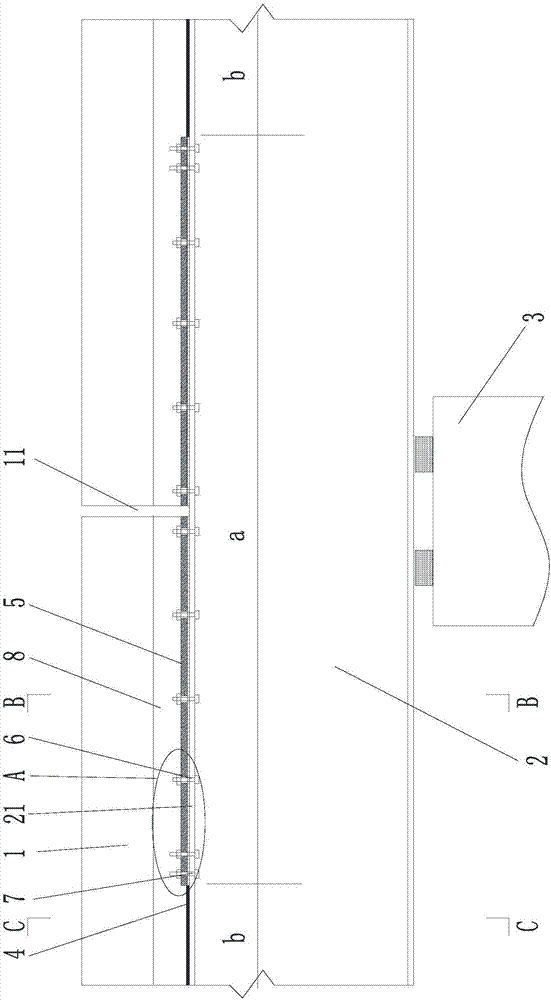
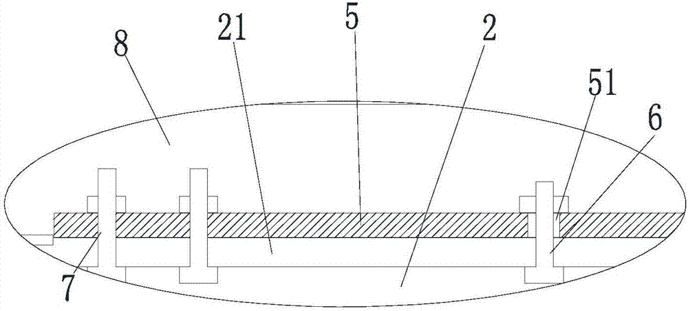
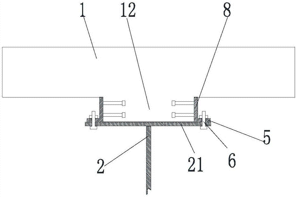
[0019] figure 1 It is a structural schematic diagram of the present invention, figure 2 for figure 1 Enlarged view at A, image 3 for figure 1 B-B direction sectional schematic diagram, Figure 4 for figure 1 C-C section schematic diagram, as shown in the figure: the steel-concrete composite continuous girder bridge for releasing the tensile stress of the bridge slab in this embodiment includes a steel girder 2 and a concrete bridge slab 1 fixed on the steel beam 2, the concrete The bridge slab 1 is provided with a transverse through-through fracture 11 above the middle pier 3 corresponding to the continuous girder bridge, and the concrete bridge slab 1 and the steel girder 2 are arranged on both sides of the transverse through-through fracture 11 (along the longitudinal two sides of the bridge). Side) The local section has relatively longitudinal expansion and contraction deformation, that is, the section between the concrete bridge slab 1 and the steel beam 2 can slide...


PUM


Abstract

The invention discloses a steel-concrete combined continuous beam bridge for releasing pulling stress of a carriageway slab. The steel-concrete combined continuous beam bridge comprises a steel beam and the concrete bridge carriageway slab fixed on the steel beam. A transverse penetrating breaking joint is formed in the position, above an intermediate pier corresponding to the continuous beam bridge, of the concrete bridge carriageway slab. The local sections of the two sides of the transverse penetrating breaking joint have relative longitudinal telescoping deformation between the concrete bridge carriageway slab and the steel beam. The pulling stress generated from high negative bending moment is unloaded and transferred to the steel beam, pulling of the concrete bridge carriageway slab is avoided, the stressing state of the whole steel-concrete combined beam is optimized, performance superiority of steel materials and concrete can be played, vertical load of the carriageway slab is directly transmitted to the steel beam, it is ensured that the carriageway slab does not generate abnormal vertical deformation, stress concentration and fatigue problems of the carriageway slab and the steel beam from fixing to separating in a junction connecting local area, construction and a construction technology of the carriageway slab are greatly simplified, and the whole stress performance of the bridge is improved, the using period of the beam bridge is prolonged, and the construction and maintaining cost are reduced.

Description

technical field [0001] The invention belongs to the field of bridge engineering equipment, in particular to a steel-concrete combined continuous girder bridge for releasing the tensile stress of the bridge slab. Background technique [0002] The steel-concrete composite continuous girder bridge has a series of advantages such as smooth running, good performance, economical materials, and convenient factory and standardized construction. The common construction method of the existing steel-concrete composite continuous girder bridge is to install the steel girder in place on the pier, hoist the prefabricated concrete bridge slab in place on the steel girder, combine the concrete with cast-in-place to form a steel-concrete composite girder bridge, and then pass Tensile prestressed steel bars exert precompressive stress on the concrete bridge slab in the negative moment section. [0003] The "Segmental Continuous Prefabrication—Steel-Concrete Composite Beam Bridge and Its Cons...

Claims


Application Information

Patent Timeline
Patent Type & Authority Applications(China)
IPC IPC(8): E01D1/00E01D19/00
Inventor 周志祥邓国军乔心格邵帅
Owner CHONGQING JIAOTONG UNIVERSITY
Why Eureka
Try Eureka