Automatic rubber tubulating machine

A take-over machine and automatic technology, applied in the field of machinery, can solve the problems of high manufacturing cost, difficult operation, large floor space, etc., and achieve the effect of reducing production cost, compact and simple structure, and reduced occupied area.

Inactive Publication Date: 2017-12-15
WUXI WELL ELECTRO HYDRAULIC EQUIP CO LTD
View PDF11 Cites 0 Cited by
  • Summary
  • Abstract
  • Description
  • Claims
  • Application Information

AI Technical Summary

Problems solved by technology

[0002] The dimensional accuracy and shape and position accuracy of the rubber joints are all required to be high. The existing automatic rubber joint machines generally adopt a separate workbench assembly line operation method, which occupies a large area and has low work efficiency.
Some adopt the round table assembly line operation method, and the work efficiency also has room for development. The rubber joints in the prior art have low efficiency and are easy to block. demanding, not safe
[0003] There are two common processing methods for connecting pipes. One is to cut them out with one knife through machine tools. This method has the highest precision, but the processing efficiency is the lowest and the manufacturing cost is very high. The other is to punch out through precision stamping devices. The processing efficiency of the method is higher than that of the machine tool, but due to the limitation of the technical level of the entire air-conditioning parts manufacturing industry at this stage, the stamping machine commonly used for pipe processing not only has poor processing quality, but also has a high scrap rate and a high degree of automation. not tall

Method used


Image

  • Automatic rubber tubulating machine
  • Automatic rubber tubulating machine

Examples


Embodiment

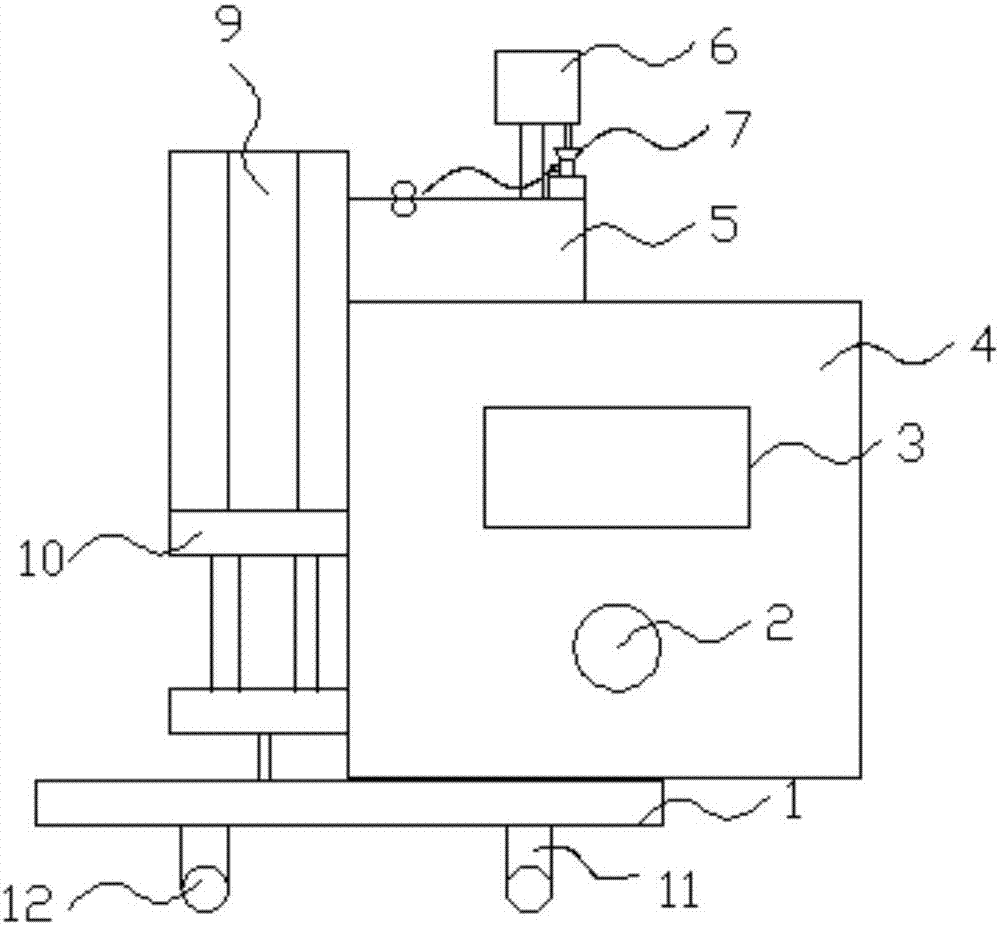
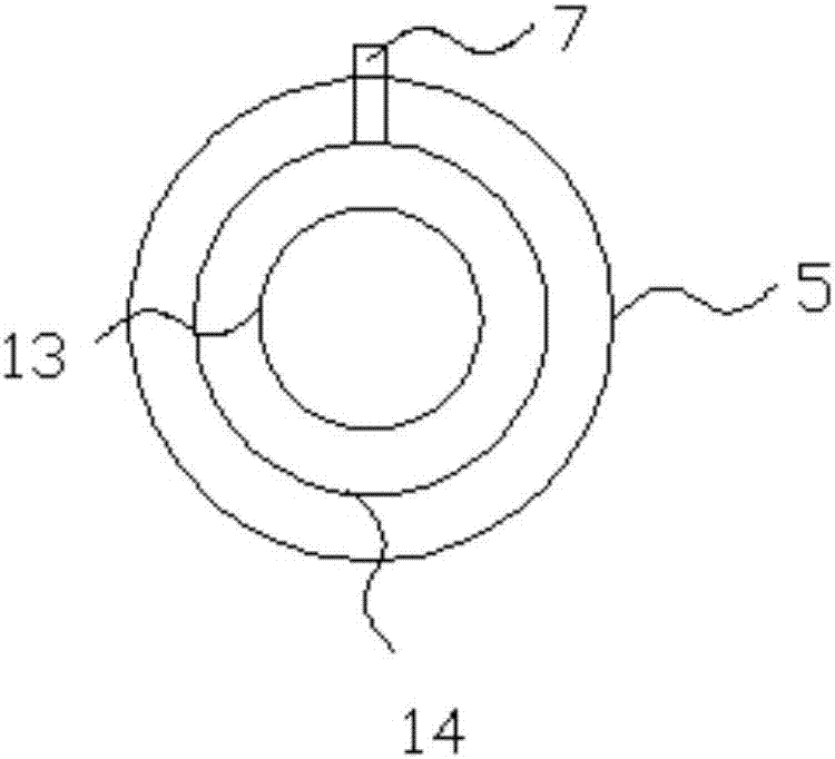
[0020] Such as Figure 1-2 As shown, an automatic rubber connecting machine includes a base 1, an LED light 2, a display screen 3, a chassis 4, a connecting point 5, a paint bucket 6, a funnel 7, an automatic button 8, a rotating shaft 9, a bracket 10, and a fixed wheel device 11 And the wheel 12, characterized in that the base 1 is provided with the bracket 10 and the case 4, the top of the case is provided with the connection part 5, and the connection part 5 is provided with the funnel 7.

[0021] The connection 5 includes an inner core 13 and an outer wall 14, the drain 7 is embedded in the connection 5 and connected with the outer wall 14, the support 10 is provided with the rotating shaft 9, and the rotating shaft 9 is connected to the outer wall 14. The inner core 13 is connected, the bottom of the paint bucket 6 is connected with the funnel 7, the automatic button 8 is provided on one side of the funnel 7, and the display screen 3 and the LED lamp 2, the bottom of the...


PUM


Abstract

The invention relates to an automatic rubber tubulating machine. The automatic rubber tubulating machine comprises a base, an LED lamp, a displaying screen, a machine box, a tubulating part, a pigment bucket, a funnel, an automatic button, a rotating shaft, a bracket, a wheel-fixing device and wheels; the bracket and the machine box are arranged on the base, the tubulating part is arranged on the top of the machine box, and the funnel is arranged on the tubulating part; the tubulating part comprises an inner core and an outer wall; the funnel is inlaid in the tubulating part and is connected with the outer wall; the bracket is provided with the rotating shaft which is connected with the inner core; the funnel is connected with the bottom of the pigment bucket, and the automatic button is arranged on one side of the funnel; the displaying screen and the LED lamp are arranged on one side of the machine box; and the wheel-fixing device is arranged at the bottom of the base, and no less than four wheels are arranged at the bottom of the wheel-fixing device. According to the automatic rubber tubulating machine, the connecting technique is good, quality is standard, the automation degree is high, automatic feeding can be ahicved, potential safety hazards during operating of workers are eliminated, so that safety of the workers is guaranteed powerfully; and the structure is compact and simple, installation and maintenance are very convenient, and working is stable and smooth.

Description

technical field [0001] The invention relates to an automatic rubber pipe joint machine, which belongs to the technical field of machinery. Background technique [0002] The dimensional accuracy and shape and position accuracy of the rubber joints are all required to be high. The existing automatic rubber joint machines generally adopt a separate workbench assembly line operation method, which occupies a large area and has low work efficiency. Some adopt the round table assembly line operation method, and the work efficiency also has room for development. The rubber joints in the prior art have low efficiency and are easy to block. It is demanding and not safe. [0003] There are two common processing methods for connecting pipes. One is to cut them out with one knife through machine tools. This method has the highest precision, but the processing efficiency is the lowest and the manufacturing cost is very high. The other is to punch out through precision stamping devices. ...

Claims


Application Information

Patent Timeline
Patent Type & Authority Applications(China)
IPC IPC(8): B29C65/48
CPCB29C65/48B29C66/522
Inventor 解正云
Owner WUXI WELL ELECTRO HYDRAULIC EQUIP CO LTD
Why Eureka
Try Eureka