
Laser drive mechanism and 3D printer

A technology of laser drive and drive mechanism, which is applied in the field of 3D printing, can solve the problems of small printing range, small size of forming components, limiting the development and application of process technology, etc., and achieve the effect of large printing range

Pending Publication Date: 2017-12-15
窦鹤鸿
View PDF10 Cites 3 Cited by
  • Summary
  • Abstract
  • Description
  • Claims
  • Application Information

AI Technical Summary

Problems solved by technology

This structure makes the printing range of the 3D printer smaller, resulting in a relatively smaller size of the molded component
Greatly limit the development and application of this technology

Method used


Image

  • Laser drive mechanism and 3D printer
  • Laser drive mechanism and 3D printer
  • Laser drive mechanism and 3D printer

Examples


Embodiment

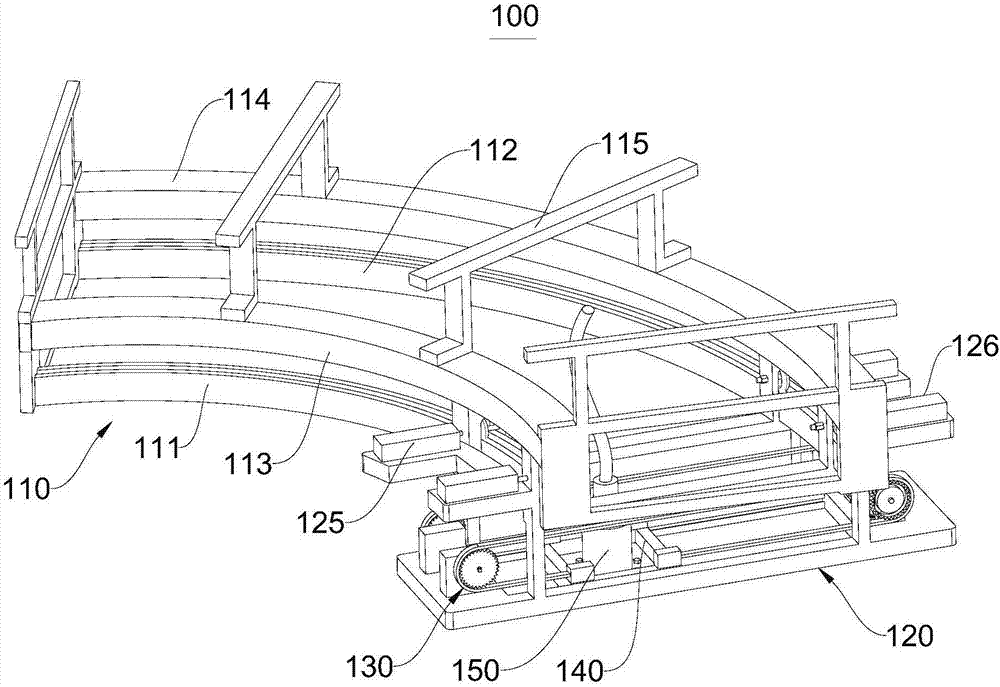
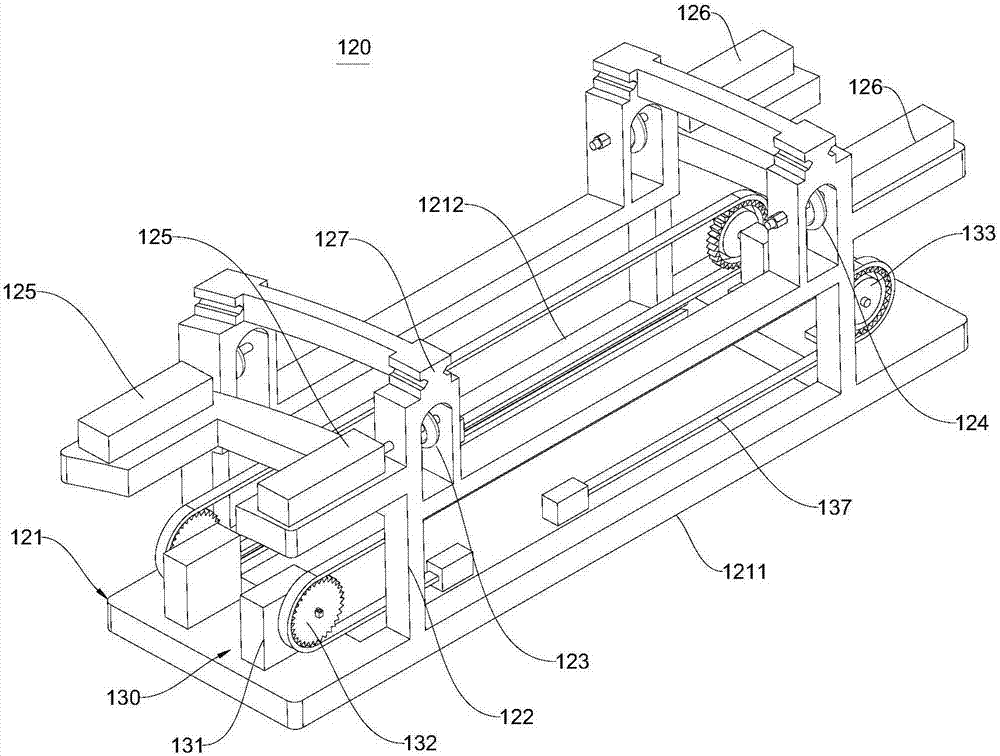
[0044] figure 1 It is a schematic diagram of the overall structure of the laser driving mechanism 100 in the embodiment of the present invention. Please refer to figure 1, the present embodiment provides a laser driving mechanism 100 , which includes a track assembly 110 , a parent car 120 , a sub-car 140 and a laser emitting device 150 disposed on the sub-car 140 . The mother car 120 is movably connected to the track assembly 110 and can move along the path defined by the track assembly 110 ; the child car 140 is movably connected to the mother car 120 and can move linearly relative to the mother car 120 . Therefore, the laser emitting device 150 mounted on the sub-car 140 can have a larger printing range under the movement of the mother car 120 and the sub-car 140 .

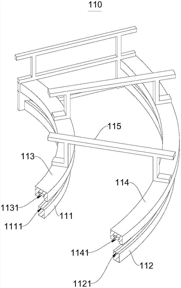
[0045] figure 2 It is a cross-sectional view of the track assembly 110 in the embodiment of the present invention. Please combine figure 1 and figure 2 , in this embodiment, the track assembly 110 inclu...


PUM


Abstract

The invention relates to the technical field of 3D print and discloses a laser drive mechanism and a 3D printer. The laser drive mechanism comprises a rail assembly, a main trolley, an auxiliary trolley and a laser emitting device. The main trolley is movably connected to the rail assembly. A guide rail of the rail assembly provides an arc movement path for the main trolley. The auxiliary trolley is movably connected to the main trolley and can move in the radial direction of the arc guide rail relative to the main trolley. The laser emitting device is arranged on the auxiliary trolley. The 3D printer comprises the laser drive mechanism and a work bench. The laser emitting device can select to conduct sintering or melting on powder printing materials on a workbench at different positions on a fan-shaped ring face (or a circular ring face) along with movement of the main trolley and the auxiliary trolley. In this way, the 3D printer with the laser drive mechanism has a wide printing range.

Description

technical field [0001] The invention relates to the technical field of 3D printing, in particular to a laser drive mechanism and a 3D printer. Background technique [0002] 3D printer, also known as three-dimensional printer (3DP), is a cumulative manufacturing technology, that is, a machine of rapid prototyping technology. It is a machine based on digital model files (CAD) and uses special wax, powdered metal or plastic and other bondable materials, a technology that creates three-dimensional objects by printing layers of adhesive materials. At this stage 3D printers are used to manufacture products. Some systems use a technique known as "laser sintering," in which powder particles are used as the printing medium. Powder particles are laid on the mold tray to form a certain thickness of powder layer, which is laser melted into a specified shape. The existing laser emitting device is set at a fixed position, and sintering or melting the powder at different positions is re...

Claims


Application Information

Patent Timeline
Patent Type & Authority Applications(China)
IPC IPC(8): B29C64/20B29C64/268B29C64/241B22F3/105B33Y30/00
CPCB33Y30/00B22F10/00B22F12/46B22F10/28Y02P10/25
Inventor 窦鹤鸿
Owner 窦鹤鸿
Learn More