
System and method for adjusting mould clamping force

A technology for adjusting the system and adjustment method, which is applied in the field of mold equipment, and can solve problems such as unstable clamping force detection, stretching amount detection sensors, expensive analog acquisition modules, and data distortion.

Active Publication Date: 2017-12-15
宁波保税区海天智胜金属成型设备有限公司
View PDF4 Cites 9 Cited by
  • Summary
  • Abstract
  • Description
  • Claims
  • Application Information

AI Technical Summary

Problems solved by technology

[0004] ① The stretch detection sensor and analog acquisition module are expensive;
[0005] ② The zero point drift of the conversion board often occurs after a long time, resulting in data distortion;
[0006] ③The anti-interference ability of the voltage-type analog signal is weak, and the fluctuation is large, resulting in unstable clamping force detection;
[0007] ④Complicated structure and difficult maintenance;
[0008] ⑤The mold adjustment process takes a long time

Method used


Image

  • System and method for adjusting mould clamping force
  • System and method for adjusting mould clamping force

Examples


Embodiment Construction

[0037] In order to make the purpose, technical solution and advantages of the present application clearer, the technical solution of the present application will be clearly and completely described below in conjunction with specific embodiments of the present application and corresponding drawings. Apparently, the described embodiments are only some of the embodiments of the present application, rather than all the embodiments. Based on the embodiments in this application, all other embodiments obtained by persons of ordinary skill in the art without making creative efforts belong to the scope of protection of this application.

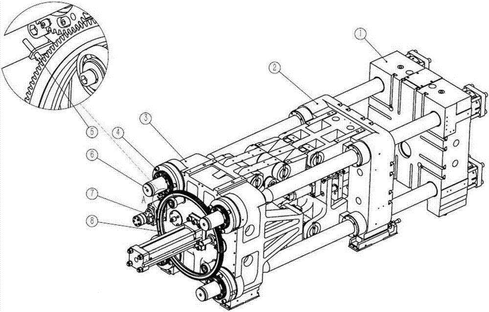
[0038] The invention discloses a mold clamping force adjustment system, which comprises a gear mechanism, a movable mold mechanism, a fixed template, a programmable controller, a hydraulic motor, and an electromagnetic induction sensor.

[0039] Specifically, this embodiment discloses a mold clamping force adjustment system for a die casting machine. ...


PUM


Abstract

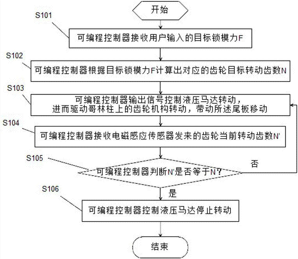
The invention discloses a method for adjusting the mould clamping force. The method comprises the following steps that A, a programmable logic controller (PLC) receives the target mould clamping force F input by a user; B, according to the target mould clamping force F, the PLC calculates the target rotating tooth number N of a corresponding gear; C, the PLC outputs a signal to control a hydraulic motor to rotate and then drives a gear mechanism on a tie bar to rotate, and a movable mould plate is driven to move; D, the PLC receives the current rotating tooth number N', sent by an electromagnetic induction sensor, of the gear; and E, when N'=N, the PLC controls the hydraulic motor to stop rotating, the process is finished, and otherwise, the step C is returned. Through a system, the mould clamping force of a machine hinging type mould closing mechanism can be automatically adjusted, the cost is effectively reduced, meanwhile, the system adopts all-digital signals, the interference or data distorting phenomenon does not occur, and the mould adjusting efficiency is greatly improved.

Description

technical field [0001] The patent of the present invention relates to the field of mold equipment, specifically a clamping force adjustment system and adjustment method. Background technique [0002] When the die-casting machine or injection molding machine is working, the extrusion molding of the mold can only be realized after the movable template and the fixed template are molded and locked. When the mold is formed, the extruded mold will generate a huge force to separate the fixed plate and the movable plate, so the equipment should provide a huge clamping force in a short time when the mold is extruded. In order to ensure the quality of the mold, it is necessary to precisely control the clamping force. [0003] In the prior art, the method of adjusting the clamping force is as follows: Use the stretch sensor to measure the stretch of the Gelin pillar, cooperate with the conversion board to convert the stretch into a 0-10v analog signal, and use the computer analog acqu...

Claims


Application Information

Patent Timeline
IPC IPC(8): B29C45/76B22D17/32
CPCB22D17/32B29C45/7653B29C2945/76702B29C2945/76869
Inventor 龙孟威徐建华王永桃韦少宇郑培黄新安
Owner 宁波保税区海天智胜金属成型设备有限公司
Learn More