
Valve base tightening device for ball valve assembly

A tensioning device and valve seat technology, applied in metal processing, metal processing equipment, manufacturing tools, etc., can solve problems such as difficulty, and achieve the effects of low cost, simple structure, and improved installation efficiency

Inactive Publication Date: 2017-12-15
WUZHONG INSTR
View PDF7 Cites 1 Cited by
  • Summary
  • Abstract
  • Description
  • Claims
  • Application Information

AI Technical Summary

Problems solved by technology

[0004] The technical problem to be solved by the present invention is: in order to solve the difficult problem of ball valve assembly in the prior art, a valve seat tensioning device for ball valve assembly is now provided

Method used


Image

  • Valve base tightening device for ball valve assembly
  • Valve base tightening device for ball valve assembly
  • Valve base tightening device for ball valve assembly

Examples


Embodiment 1

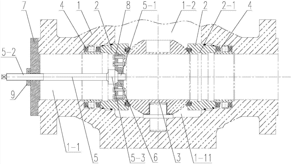
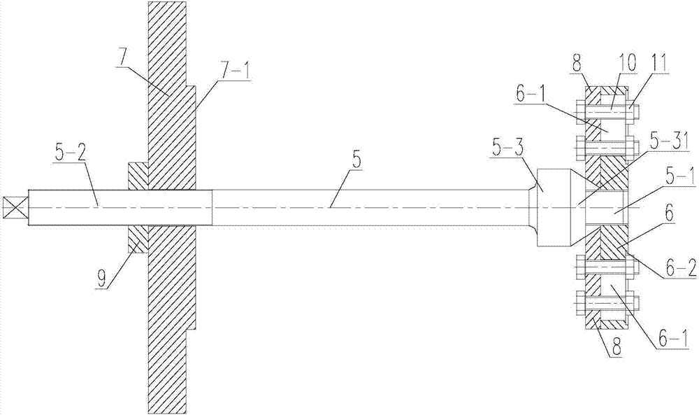
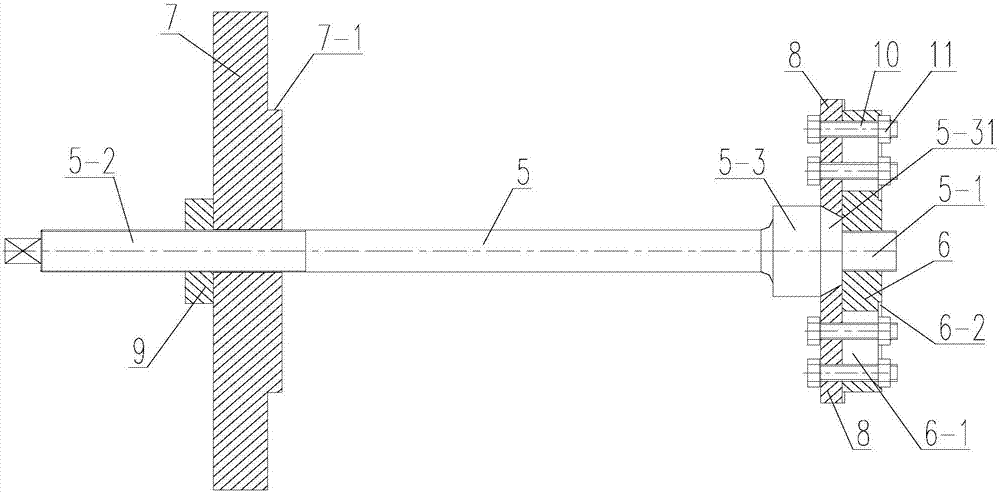
[0029] like Figure 1-6 As shown, a valve seat tensioning device for ball valve assembly, the ball valve includes a valve body 1 and a valve seat 2, the valve body 1 has a flow channel 1-1 running through it, and the valve body 1 has a ball communicating with the flow channel 1-1. The core insertion hole 1-2, the position of the flow channel 1-1 facing the ball core insertion hole 1-2 has a valve cavity 1-11 for installing the ball core 3, and the valve cavity 1-11 is along the flow channel 1-1. Both ends of the direction are provided with valve seats 2. There is an elastic element 4 between the outer side of the valve seat 2 and the valve body 1. The elastic element 4 is a spring. The tensioning device includes a pull rod 5, a base 6 and a The backing plate 7 at the end of the body 1, the backing plate 7 is sleeved on the pull rod 5;

[0030] The front end of the pull rod 5 has a push section 5-3, the front end of the push section 5-3 is extended with a first threaded sectio...


PUM


Abstract

The invention relates to the technical field of ball valves, in particular to a valve base tightening device for ball valve assembly. The tightening device comprises a pull rod, a base and a pad plate used for abutting against the end of a valve body, and the pad plate is arranged on the pull rod in a sleeving mode; a push section is arranged at the front end of the pull rod, a first thread section is arranged at the front end of the push section in an outward extending mode, a second thread section is arranged at the tail end of the pull rod, and the first thread section is in threaded connection with the base; several adjusting plates are arranged on the base along the push section in a winding mode, a conical surface is arranged on the side wall of the push section, and the side faces of the sides, close to the push section, of the adjusting plates are matched with the conical surface; the second thread section at the tail end of the pull rod is in threaded connection with a screwing nut. Firstly, by rotating the pull rod, the adjusting plates on the base are pushed out in the radial direction and clamped into technological grooves of a valve base, drive connection of the valve base and the pull rod is achieved, then the screwing nut on the pull rod is screwed, therefore the pull rod drives the valve base to move outwards, and a spring between a valve body and the valve base is compressed.

Description

technical field [0001] The invention relates to the technical field of ball valves, in particular to a valve seat tensioning device for ball valve assembly. Background technique [0002] With the increasing development of deep-sea oil and natural gas extraction technology in my country and the continuous progress of exploration work, the demand for large-diameter and high-pressure valves is increasing. With the improvement of seals and materials, the reliability of ball valves has reached a Apex, they are seen as a viable option to replace gate valves in many deep sea applications. [0003] The existing underwater ball valve adopts the overall top-loading structure, and the leakage point is less than that of the general valve, but the processing and assembly of the top-loading ball valve are significantly more difficult. After the spring between the two valves is compressed, the ball core can be placed between the two valve seats in the valve body, resulting in time-consumin...

Claims


Application Information

Patent Timeline
Patent Type & Authority Applications(China)
IPC IPC(8): B23P19/04
CPCB23P19/04
Inventor 马玉山秦新文刘勇张耀华王媛媛
Owner WUZHONG INSTR
Learn More