
Sharding type wind tower sharding cutting machine and cutting method

A slicing and cutting machine technology, used in welding equipment, gas flame welding equipment, metal processing equipment, etc., can solve the problem of increasing the workload, labor intensity and attention of workers, difficulty in positioning the arc surface, and wrong cutting lines. and other problems, to achieve the effect of reducing labor intensity and attention, improving operability, and reducing workload

Pending Publication Date: 2017-12-15
SUZHOU TITAN NEW ENERGY TECH CO LTD
View PDF0 Cites 0 Cited by
  • Summary
  • Abstract
  • Description
  • Claims
  • Application Information

AI Technical Summary

Problems solved by technology

However, there are the following disadvantages in the process of use: the linear track is only suitable for flat plate cutting, and it is not suitable for linear cutting on the circular arc surface due to the difficulty in positioning the arc surface along the axis of the cylinder; the orbital linear cutting equipment is limited Due to the length of the track, it is only suitable for short-distance straight-line cutting; when the track needs to be spliced ​​​​during the cutting process due to the cutting length, the workload, labor intensity and attention of the workers will be increased, and at the same time, the cutting line may appear wrong due to uneven splicing

Method used


Image

  • Sharding type wind tower sharding cutting machine and cutting method
  • Sharding type wind tower sharding cutting machine and cutting method
  • Sharding type wind tower sharding cutting machine and cutting method

Examples


Embodiment Construction

[0028] Embodiments of the present invention are described in detail below, examples of which are shown in the drawings, wherein the same or similar reference numerals designate the same or similar elements or elements having the same or similar functions throughout. The embodiments described below by referring to the figures are exemplary only for explaining the present invention and should not be construed as limiting the present invention.

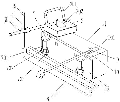
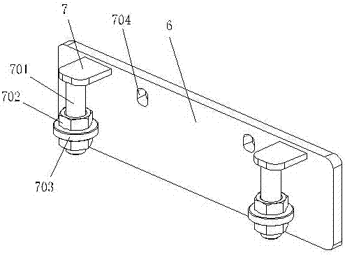
[0029] Refer below Figure 1 to Figure 5 Describe a fragmented wind tower fragment cutting machine according to an embodiment of the present invention, including a mobile body 1, wherein a longitudinal flange 8 is provided on the side of the mobile body 1 to allow the mobile body 1 to be displaced along a certain track, and the mobile The wheel side plate 6 is arranged between the body 1 and the longitudinal flange 8, the wheel side plate 6 is provided with a screw rod 701, the screw rod 701 is connected with a bearing 703, the bearing 7...


PUM


Abstract

The invention relates to a sharding type wind tower sharding cutting machine and a cutting method thereof. The sharding type wind tower sharding cutting machine comprises a movable body, wherein the side of the movable body is provided with a longitudinal flange capable of making the movable body move along a certain trajectory; a wheel depending side plate is arranged between the movable body and the longitudinal flange, and is provided with a thread rod which is connected with a bearing; the bearing is arranged on the outer side face of the longitudinal flange; the movable body is provided with a cutting gun nozzle assembly; and one end of the cutting gun nozzle assembly extends into the longitudinal flange. The sharding type wind tower sharding cutting machine has the beneficial effects that the movable body is fully utilized to move along the longitudinal flange, under the condition that a straight track is not used, linear cutting is completed, and operability of the equipment is improved; cutting is made to be not limited by the length of the track and the shape of a tower barrel, full-length cutting is performed, and the workload of a worker is reduced; and besides, the movable body can pass through a combination of the wheel depending side plate and the bearing to achieve side face movement on the longitudinal flange, and therefore the labor intensity and the attentiveness are relieved, and meanwhile the possibility of misalignment of cutting is reduced.

Description

technical field [0001] The invention specifically relates to a segmented wind tower segment cutting machine, in particular to a wind tower linear wind tower cutting machine with side wheel plates. Background technique [0002] The operation steps of the existing cutting equipment are as follows: put the track on the steel plate and keep it parallel to the cutting line; put the cutting trolley on the track and adjust the cutting nozzle to roughly align with the cutting line; ignite, turn on the gas and one of the supporting gas , adjust the air line of the cutting nozzle to align with the cutting line and adjust the distance between the cutting nozzle and the steel plate, and then open another supporting gas to cut the steel plate. However, there are the following disadvantages in the process of use: the linear track is only suitable for flat plate cutting, and it is not suitable for linear cutting on the circular arc surface due to the difficulty in positioning the arc surfa...

Claims


Application Information

Patent Timeline
IPC IPC(8): B23K7/10B23K7/00
CPCB23K7/00B23K7/102
Inventor 李如愿
Owner SUZHOU TITAN NEW ENERGY TECH CO LTD
Learn More