Visualized remote control feeder

A technology of remote control and control system, applied in the field of feeding machines, can solve the problems of too many equipment and long time required to go out, and achieve the effect of saving space and reducing supporting equipment.

Pending Publication Date: 2017-12-15
郝巴雅斯胡良
View PDF7 Cites 3 Cited by
  • Summary
  • Abstract
  • Description
  • Claims
  • Application Information

AI Technical Summary

Problems solved by technology

Secondly, the mode of pulverizer-conveyor-mixer-conveyor-automatic feeding machine requires too much equipment
In addition, although this mode relieves the daily labor of the breeders, it still requires the breeders to operate the equipment every day and then monitor the operation of the equipment. Since the pastoral areas are far away from towns, it takes a long time to go out. freedom is a focus of this program

Method used


Image

  • Visualized remote control feeder
  • Visualized remote control feeder
  • Visualized remote control feeder

Examples


Embodiment Construction

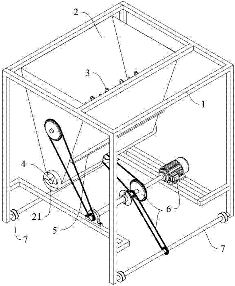
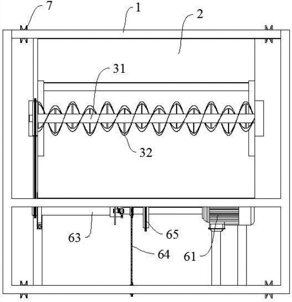
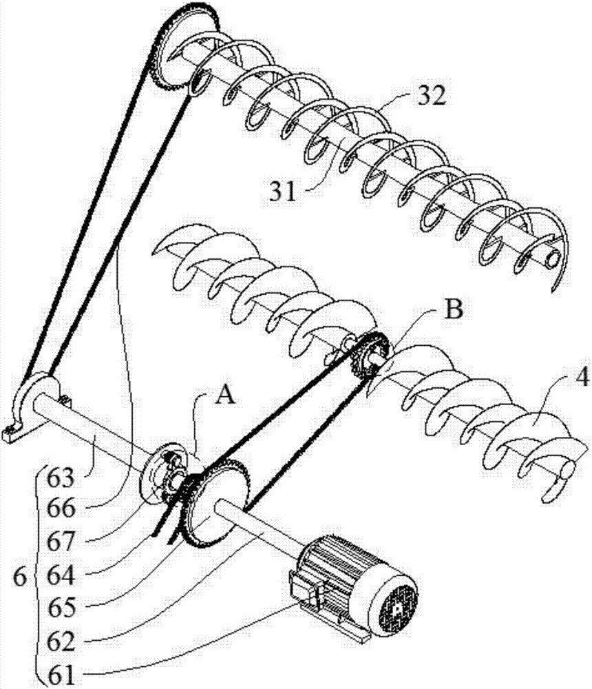
[0021] as attached Figure 1~6 As shown, a feeding machine with visual remote control includes: frame 1, hopper 2, stirring mechanism 3, discharging mechanism 4, water adding system (not shown), gate 5, weighing system (not shown) , camera (not shown), control system (not shown), drive mechanism 6, travel mechanism 7; mixing mechanism 3 is arranged in the middle part of hopper 2, and both sides of hopper 2 bottom have discharge port 21, and discharge mechanism 4 is arranged In the lower part of the hopper 2, a gate 5 is provided between the stirring mechanism 3 and the discharge mechanism 4. When the gate 5 is closed, the hopper 2 is divided into upper and lower parts. When stirring, the gate 5 needs to be closed to prevent the forage from being compacted downward; add water The system is used to add water to the upper chamber of the hopper 2. The traveling mechanism 7 is arranged at the lower part of the frame 1. The driving mechanism 6 provides power for the stirring mechani...


PUM


Abstract

Disclosed is a visualized remote control feeder. The feeder mainly comprises a hopper, a stirring mechanism, a discharging mechanism, a water adding system, a gate, a weighing system, cameras, a control system, a driving mechanism and a walking mechanism. The stirring mechanism is arranged in the middle of the hopper, discharging outlets are formed in the two sides of the lower portion of the hopper, the discharging mechanism is arranged at the lower portion of the hopper, the gate is arranged between the stirring mechanism and the discharging mechanism, the walking mechanism is arranged at the lower portion of the machine frame, the driving mechanism provides power for the stirring mechanism, the discharging mechanism and the walking mechanism, the cameras are arranged at the front and back ends of a machine frame, the weighing system is arranged on a machine frame stand column, the weighing system, the cameras and the control system are electrically connected, and the control system comprises a wireless signal transceiving module. By reasonably adopting the feeder hopper, the previous stirrer-conveyor links are omitted, and corollary equipment is omitted, so that the occupied place is saved; unattended remote control is achieved through the weighing system, the cameras and the control system.

Description

Technical field: [0001] The invention relates to the technical field of feeding machines, in particular to a visual remote-controlled feeding machine. Background technique: [0002] In recent years, animal husbandry has developed rapidly in house breeding, which has also brought a large number of heavy and harsh daily tasks to the breeders, mainly feed preparation and excrement cleaning. Previously, the whole process of feeding feed to livestock in pastoral areas was done manually. First, the feed was crushed, then an appropriate amount of water was added, and then manually stirred evenly before being sent to the feeding trough and evenly sprinkled in the trough. For this reason, the patent with authorized notification number CN202435931E invented a kind of automatic feeding machine. The automatic feeding machine is arranged on the track. - Conveyor-mixer-conveyor-automatic feeding machine, which greatly improves the level of mechanization and liberates the feeders from hea...

Claims


Application Information

Patent Timeline
Patent Type & Authority Applications(China)
IPC IPC(8): A01K5/02
CPCA01K5/02
Inventor 哈斯达来郝巴雅斯胡良辛雷勇魏世军刘斌郭庆兰
Owner 郝巴雅斯胡良
Why Eureka
Try Eureka