
Flexible display device

A flexible display device and display area technology, applied in identification devices, static indicators, instruments, etc., can solve the problems of wire breakage, flexible display panel failure, easy breakage, etc., to reduce the horizontal distance and facilitate narrow borders Design, the effect of improving yield

Active Publication Date: 2017-12-12
SHANGHAI TIANMA MICRO ELECTRONICS CO LTD
View PDF7 Cites 39 Cited by
  • Summary
  • Abstract
  • Description
  • Claims
  • Application Information

AI Technical Summary

Problems solved by technology

After the flexible display panel is fabricated, it is necessary to separate the flexible display panel from the rigid substrate. During the separation process, due to the stress mismatch between the film layers of the flexible display panel, it is easy to break the wires, and the closer the The traces on the edge of the flexible display panel are more likely to break, and the breakage of the traces is likely to cause the failure of the flexible display panel

Method used


Image

  • Flexible display device
  • Flexible display device
  • Flexible display device

Examples


Embodiment Construction

[0033] Various exemplary embodiments of the present invention will now be described in detail with reference to the accompanying drawings. It should be noted that the relative arrangements of components and steps, numerical expressions and numerical values ​​set forth in these embodiments do not limit the scope of the present invention unless specifically stated otherwise.

[0034] The following description of at least one exemplary embodiment is merely illustrative in nature and in no way taken as limiting the invention, its application or uses.

[0035] Techniques, methods and devices known to those of ordinary skill in the relevant art may not be discussed in detail, but where appropriate, such techniques, methods and devices should be considered part of the description.

[0036] In all examples shown and discussed herein, any specific values ​​should be construed as exemplary only, and not as limitations. Therefore, other instances of the exemplary embodiment may have dif...


PUM


Abstract

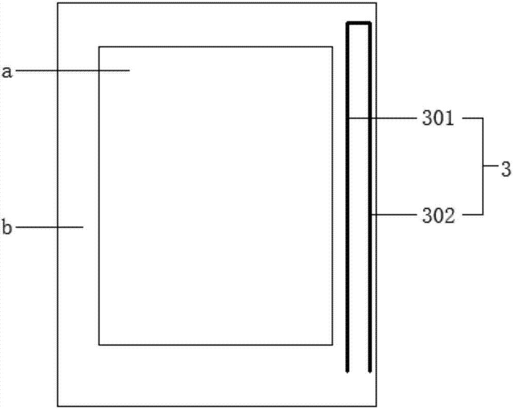
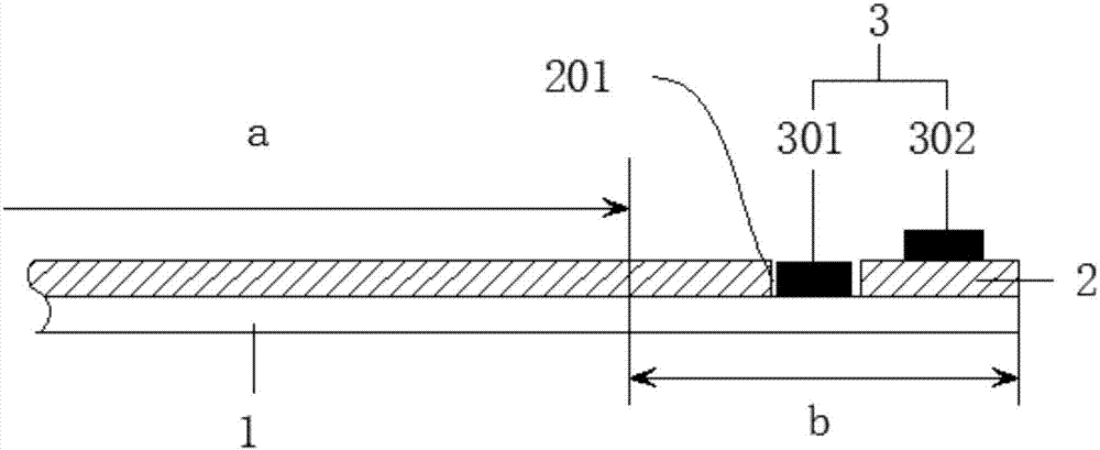
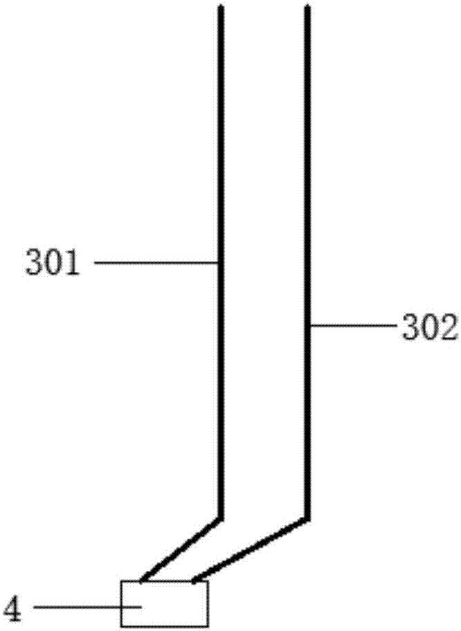
The invention discloses a flexible display device which comprises a display area and a non-display area encircling the display area, a first flexible substrate, an inorganic layer arranged on the first flexible substrate, and grounding wires arranged on the inorganic layer, wherein the grounding wires are arranged in the non-display area and form a detection circuit; at least two grounding wires are arranged in the non-display area on the same side of the display area at least; the at least two grounding wires comprise at least one first grounding wire and at least one second grounding wire; the inorganic layer is provided with a groove; the first grounding wire is arranged in the groove; the second grounding wire is arranged on the surface of the inorganic layer. According to the flexible display device disclosed by the invention, crack positions can be judged by the detection circuit, whether the cracks exist on the inorganic layer and on the first flexible substrate can be judged, and the detection rate of risk products is improved; meanwhile, since the first grounding wire is positioned in the groove, and the second grounding wire is positioned on the surface of the inorganic layer, the horizontal distance among the various grounding wires can be reduced, and the narrow bezel design of the flexible display device is promoted.

Description

technical field [0001] The invention belongs to the field of display technology, and in particular relates to a flexible display device. Background technique [0002] With the continuous development of display technology, flexible display panels will soon become the mainstream in the display field due to their thin, light, bendable, and impact-resistant features. [0003] The flexible display panel includes: a base layer and an inorganic layer, wherein the inorganic layer plays a buffer role. When the flexible display panel is manufactured, the flexible material polyimide (PI) liquid is first coated on the rigid substrate (such as a glass substrate) to form a flexible base layer, and then the inorganic layer, display device and Various wiring, etc. After the flexible display panel is fabricated, it is necessary to separate the flexible display panel from the rigid substrate. During the separation process, due to the stress mismatch between the film layers of the flexible d...

Claims


Application Information

Patent Timeline
IPC IPC(8): G09G3/00G09F9/30
CPCG09F9/301G09G3/006G06F3/04164H10K59/131H10K77/111
Inventor 柴慧平杜凌霄丁洪杨康
Owner SHANGHAI TIANMA MICRO ELECTRONICS CO LTD
Learn More