A vibration test system and an analysis method for vibration signal time domain waveforms thereof

A vibration signal and time-domain waveform technology, applied in the measurement of ultrasonic/sonic/infrasonic waves, measuring devices, instruments, etc., can solve the problem of inability to analyze multiple channels synchronously, synchronous processing of multiple complex algorithms, inability to obtain phase information, and complex map making process etc., to make up for the limitations of incomplete information representation, simplify the operation of the map making process, and enrich the effect of phase information

Inactive Publication Date: 2017-12-12
SHENZHEN YATEKS OPTICAL ELECTRONICS TECH CO LTD
View PDF12 Cites 3 Cited by
  • Summary
  • Abstract
  • Description
  • Claims
  • Application Information

AI Technical Summary

Problems solved by technology

The process of making maps for these methods is complex and requires the operation of complex algorithms
When multiple channels collect data at the same time, it will take up a lot of computing resources and have high requirements on the computing power of the processor of the analyzer. However, most analyzers cannot perform multi-channel synchronous analysis and synchronous processing of multiple complex algorithms.
At the same time, reading pictures and reading spectrum requires professional training, which is not convenient f...

Method used


Image

  • A vibration test system and an analysis method for vibration signal time domain waveforms thereof
  • A vibration test system and an analysis method for vibration signal time domain waveforms thereof
  • A vibration test system and an analysis method for vibration signal time domain waveforms thereof

Examples


Embodiment Construction

[0041] In order to make those skilled in the art more clearly understand the purpose, technical solutions and advantages of the present invention, the present invention will be further elaborated below in conjunction with the drawings and embodiments, and similar component numbers in the drawings represent similar components. Apparently, the embodiments described below are only a part of the embodiments of the present invention, rather than all the embodiments. Based on the embodiments of the present invention, all other embodiments obtained by persons of ordinary skill in the art without making creative efforts belong to the protection scope of the present invention.

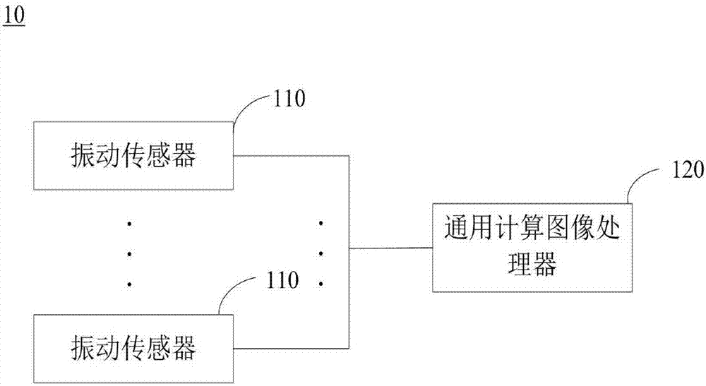
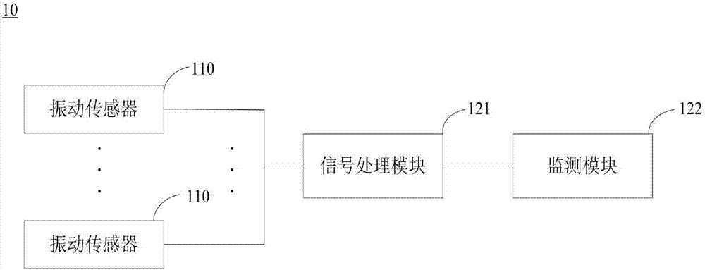
[0042] refer to figure 1 and figure 2 , the vibration measurement system 10 of the present invention is used for a rotating machine, and the vibration measurement system 10 includes a plurality of vibration sensors 110 and a general computing image processor 120 .

[0043] A plurality of vibration sensors 11...


PUM


Abstract

The invention provides a vibration test system used for rotary machines. The vibration test system comprises a plurality of vibration sensors used for acquiring multiple paths of vibration signals of a rotary machine and a general purpose computation image processor used for processing, display, computation and analysis of the multiple paths of vibration signals. The vibration sensors include eddy current displacement sensors used for acquiring key phase point signals. The general purpose computation image processor comprises a signal processing module used for conditioning, analog-digital conversion and encoding of the vibration signals and a monitoring module which displays the multiple paths of processed vibration signals in the time domain waveform image form and performs computation and analysis on the signals. The vibration test system has the advantages that the eddy current displacement sensors and the general purpose computation image processor cooperate to acquire vibration signals with key phase information for field analysis and judgment, so that multiple paths of vibration signals can be analyzed and processed synchronously and the practicality is great. The invention also provides an analysis method for vibration signal time domain waveforms of the vibration test system.

Description

technical field [0001] The invention relates to a collection system and an analysis method for a vibration signal of a rotor of a rotating machine, in particular to a vibration measurement system and a method for analyzing the time-domain waveform of the vibration signal. Background technique [0002] Rotating machinery will generate vibration and noise during the rotation process, which is the main cause of product and equipment failures. The online monitoring technology of rotating machinery is one of the important means to understand the operating status of equipment and ensure the safe operation of equipment. The collection and analysis of rotor vibration signals is one of the effective means to understand the operation status of equipment. [0003] Portable vibration analyzers currently on the market can directly collect and display time-domain and frequency-domain diagrams of rotor vibration signals, and more advanced analyzers can provide various methods for rotor sig...

Claims


Application Information

Patent Timeline
IPC IPC(8): G01H11/06
CPCG01H11/06
Inventor 张静秋刘先名王桃兰邹海娟马天悦郑翔
Owner SHENZHEN YATEKS OPTICAL ELECTRONICS TECH CO LTD
Why Eureka
Try Eureka