Cloth swinging device on side of dyeing machine

A dyeing machine and cloth board technology, applied in the field of dyeing machines, can solve problems such as affecting dyeing quality, unsmooth running and knotting, etc., to ensure the effect of water separation, improve running state, and reduce liquor ratio.

Pending Publication Date: 2017-12-12
FOSHAN SON TECH PRECISION MACHINERY
View PDF10 Cites 1 Cited by
  • Summary
  • Abstract
  • Description
  • Claims
  • Application Information

AI Technical Summary

Problems solved by technology

[0002] Most of the existing dyeing machines use the left and right arrangement devices to stack the fabrics in the cloth storage tank. The stacking state of the fabrics in the cloth storage tank directly affects the state of the running machine and the dyeing quality. Especially, for the existing fabric storage along the The fabric arrangement device that swings in the left and right directions of the trough, when stacking fabrics, there are still phenomena of pressing, knotting and disordered fabrics caused by poor stacking of the front and rear, resulting in unsmooth running of the machine and affecting the dyeing quality

Method used


Image

  • Cloth swinging device on side of dyeing machine
  • Cloth swinging device on side of dyeing machine
  • Cloth swinging device on side of dyeing machine

Examples


Embodiment 1

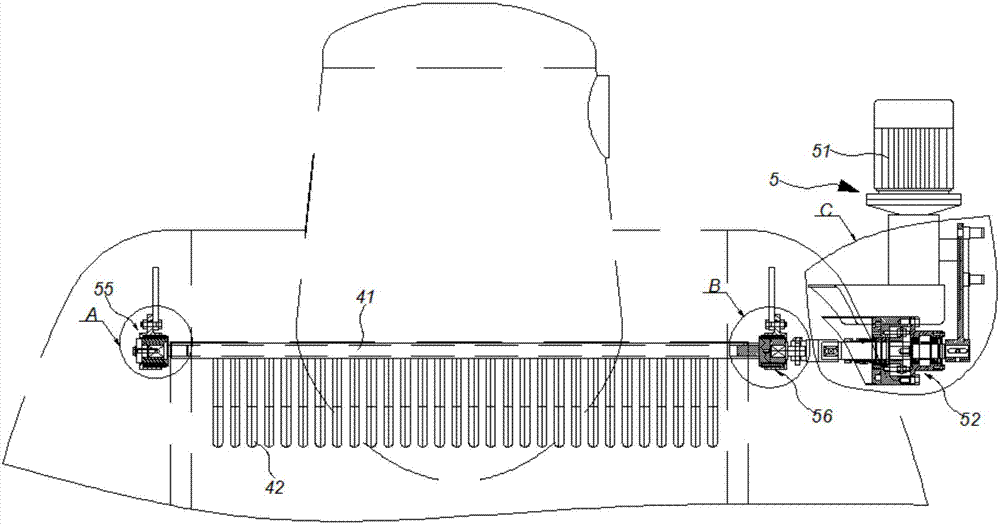
[0023] like figure 1 , 5 As shown, the arrangement device on the side of the dyeing machine includes a cylinder body 1, a cloth storage tank 2, a cloth guide pipe 3, a cloth flap 4 and a swing mechanism 5, and the cloth storage tank 2, cloth guide pipe 3, and cloth flap 4 are built into the cylinder body 1. The output end of the cloth guide pipe 3 is placed in the cloth storage tank 2 opposite to the cloth flap 4. The cloth clapping plate 4 includes a main shaft 41 and pipe teeth 42. The main shaft 41 is arranged along the left and right directions of the cloth storage tank 2. A plurality of parallel pipe teeth 42 are arranged below the main shaft 41, preferably 30. Between adjacent pipe teeth 42 The pitch is 5 mm to 35 mm, preferably 15 mm.

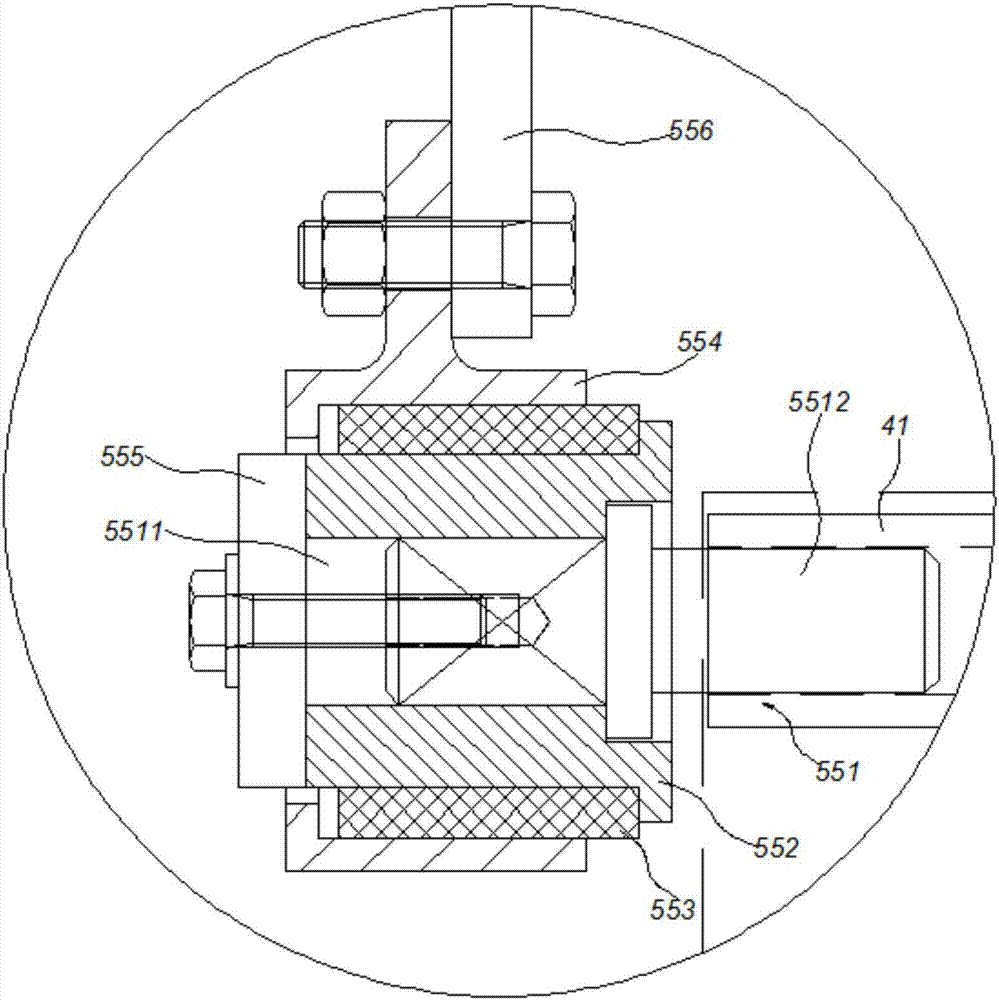
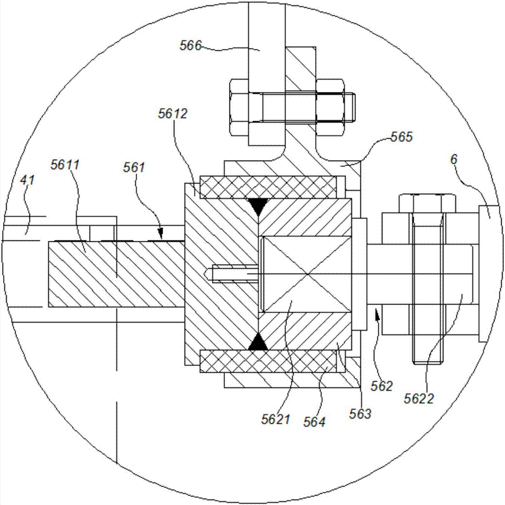
[0024] like figure 1 , 4 , 5, the swing mechanism 5 includes a reduction motor 51, a side swing shaft combination 52 and a linkage mechanism 53, the reduction motor 51 is a spur gear reduction motor, the reduction motor 51 is install...

Embodiment 2

[0030] like Figure 6 , 7As shown, the difference between this embodiment and Embodiment 1 lies in the link mechanism 53. The link mechanism 53 of this embodiment includes a second crank 53a, a pull rod 53b, a second rocker 53c, a third rocker 53d, a second Connecting rod 53e and the 4th rocking bar 53f, reduction motor 51 are connected second crank 53a by A-type round head common flat key, the rear end of pull rod 53b is connected second rocking bar 53c by anti-thread nut, ball bearing, and the rear end of pull rod 53b The front end is connected to the second crank 53a through a straight tooth nut and a ball bearing, and the second rocker 53c is connected to the right end of the rotating shaft 52a through an A-type round head common flat key. The third rocker 53d is connected to the left end of the rotating shaft 52a through the first inner eccentric rod 53g, the third rocker 53d and the fourth rocker 53f are connected through the second connecting rod 53e, and the fourth ro...


PUM


Abstract

The invention discloses a cloth swinging device on a side of a dyeing machine. The cloth swinging device on the side of the dyeing machine comprises a cylinder body, a cloth storage tank, a cloth guiding tube, a cloth beating plate and a swinging mechanism, wherein the cloth storage tank, the cloth guiding tube and the cloth beating plate are placed in the cylinder body; the swinging mechanism is mounted on the cylinder body; an output end of the cloth guiding tube and the cloth beating plate are oppositely placed in the cloth storage tank; and the swinging mechanism is in power connection to the cloth beating plate and drives the cloth beating plate to swing in the front-back direction of the cloth storage tank in a reciprocating manner. By the cloth swinging device on the side of the dyeing machine, the cloth-water separation effect is guaranteed, the bath ratio is reduced, meanwhile, fabrics are stacked orderly, and the device runs smoothly.

Description

technical field [0001] The invention belongs to the field of dyeing machines, and in particular relates to a fabric arrangement device for stacking fabrics by swinging along the front and rear directions of a fabric storage tank. Background technique [0002] Most of the existing dyeing machines use the left and right arrangement devices to stack the fabrics in the cloth storage tank. The stacking state of the fabrics in the cloth storage tank directly affects the state of the running machine and the dyeing quality. Especially, for the existing fabric storage along the The arrangement device that swings in the left and right direction of the groove still has the phenomenon of cloth pressing, knotting and disordered cloth due to poor front and rear stacking when stacking fabrics, which leads to unsmooth running of the machine and affects the dyeing quality. Contents of the invention [0003] The purpose of the present invention is to provide a side arrangement device for a ...

Claims


Application Information

Patent Timeline
Patent Type & Authority Applications(China)
IPC IPC(8): D06B23/04
CPCD06B23/04
Inventor 郑永忠陈红军
Owner FOSHAN SON TECH PRECISION MACHINERY
Why Eureka
Try Eureka