
an angle gauge

An angle gauge and angle technology, which is applied in the direction of manufacturing tools, other manufacturing equipment/tools, grinding/polishing equipment, etc., can solve the problems of not being able to obtain the sharpening angle, non-slip, and difficult to grasp

Active Publication Date: 2020-10-20
上海盈凯工具有限公司
View PDF7 Cites 0 Cited by
  • Summary
  • Abstract
  • Description
  • Claims
  • Application Information

AI Technical Summary

Problems solved by technology

However, the mastery of the sharpening angle requires experience and is not easy to grasp.
[0003] In response to the above problems, there are currently two products in practice: the first is a product that is clamped on the back of the knife. One side of the product is used to place fingers, and the other side is fixed between the other side of the knife and the whetstone. The sharpening angle plays a role in fixing the sharpening angle. The disadvantage of this product is that the sharpening angle is unique. One product is only suitable for sharpening the blade of a knife with one face width. Other knives with different face widths may not be able to use this product. Get a proper sharpening angle, resulting in inaccurate sharpening angle, thus affecting the sharpening effect
The second type, a wedge, maintains the sharpening angle through its inclined side. This product is also the only sharpening angle. A product is only suitable for sharpening knives at one angle, and it is not non-slip. During the sharpening process Frequent movement causes the sharpening angle to change, which affects the sharpening of the blade

Method used


Image

  • an angle gauge
  • an angle gauge
  • an angle gauge

Examples


specific Embodiment 1

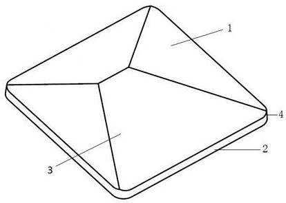
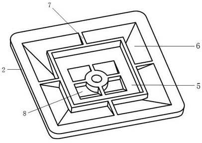
[0027] Specific embodiment 1, see figure 1 with figure 2 , The present invention provides an angle gauge, which includes a top 1, a bottom 2 below the top and a groove 5 provided at the bottom; the top 1 is spliced ​​by four inclined surfaces 3, and the inclined angles of the inclined surfaces are multiple Different angles are 14°, 17°, 20°, 25°. The lower end of the inclined surface 3 is connected with the outer edge of the bottom 2, and the outer edge of the bottom is provided with a chamfer 4. At the beginning of sharpening the blade, fingers can be placed on other slopes other than the positioning slope actually used for sharpening the blade, and by pressing the angle gauge, the adhesion between the angle gauge and the metal grindstone substrate is strengthened.

[0028] The top 1 and the bottom 2 are integrally formed of the same material.

[0029] The concave part of the bottom 2 is hollowed out 6 and has a reinforcing rib 7 for connecting the bottom 2 and the groove 5.

[00...

specific Embodiment 2

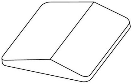
[0032] Specific embodiment 2 is basically the same as embodiment 1, see image 3 , The top part is formed by splicing two inclined surfaces, and the inclined angles of the inclined surfaces are two different angles.

[0033] The top and bottom are connected and fixed by pasting.

[0034] The groove is equipped with a magnet, and the depth of the built-in surface of the groove is the same as the thickness of the magnet.

specific Embodiment 3

[0035] Specific embodiment 3 is basically the same as embodiment 1, see Figure 4 , The top part is spliced ​​by three inclined surfaces, and the inclined angles of the inclined surfaces are three different angles.

[0036] The top and bottom are fixed by screws.

[0037] The groove is equipped with a magnet, and the depth of the built-in surface of the groove is the same as the thickness of the magnet.


PUM


Abstract

The invention provides an angle gauge. The angle gauge comprises a top part and a bottom part, wherein the bottom part is below the top part and is provided with a horizontal support; the top part is formed by splicing two or more than two oblique planes; the angles of inclination of the oblique planes comprises at least two different angles; and the lower ends of the oblique planes are connected with the outer edges of the bottom part. The angle gauge has the advantages that a plurality of sharpening angles can be provided through the multiple oblique planes of the top part, and the angle gauge can be used for grinding cutting edges of tools with different widths; and according to the technical scheme, different sizes and angles can be designed according to actual situations so as to meet the required angle requirements of the tools with different surface widths in the grinding process of the cutting edges.

Description

Technical field [0001] The invention relates to an angle gauge, in particular to a multi-angle angle gauge used for sharpening a knife edge. Background technique [0002] People use a large number of various knives in their lives and work. The knives are used for a long time, and the cutting edges are prone to wear and become dull. People tend to blunt the blade at this time. Traditional blade sharpening requires long-term accumulated experience to grasp a certain sharpening angle to ensure that the blade is sharpened. The mastering of the sharpening angle requires experience and is not easy to grasp. [0003] In view of the above problems, there are currently two products in practice: The first is a product that is clamped on the back of the knife. One side of the product is used to place fingers, and the other side is fixed between the other side of the knife and the sharpening stone. When the blade is used to fix the sharpening angle, the disadvantage of this product is that t...

Claims


Application Information

Patent Timeline
Patent Type & Authority Patents(China)
IPC IPC(8): B24B41/06B24B3/36B24D15/08
CPCB24B3/36B24B41/06B24D15/08
Inventor 王建华
Owner 上海盈凯工具有限公司
Learn More