
Silicon steel sheet stacking machine

A silicon steel sheet and stacker technology, applied in the field of silicon steel sheet production and processing, can solve the problems of low efficiency, low degree of automation, dislocation and stacking of silicon steel sheets, etc., and achieve the effect of high production efficiency and simple structure

Pending Publication Date: 2017-12-08
湖南锐科机器人技术有限公司
View PDF5 Cites 6 Cited by
  • Summary
  • Abstract
  • Description
  • Claims
  • Application Information

AI Technical Summary

Problems solved by technology

[0002] In the prior art, the processed silicon steel sheets need to be assembled, such as Figure 11 As shown, the upper yoke piece 61, the lower yoke piece 62, the left yoke piece 63, the right yoke piece 64, and the middle yoke piece 65 are all manually stacked according to the diagram, and the silicon steel stacked next time is deliberately stacked. The sheet does not coincide with the silicon steel sheet stacked last time. Figure 10 , in order to improve its performance, although there is a stacking device for silicon steel sheets at present, the existing stacking device cannot realize the dislocation and stacking of silicon steel sheets when stacking, so the current manufacturers still use manual stacking. Low, low degree of automation

Method used


Image

  • Silicon steel sheet stacking machine
  • Silicon steel sheet stacking machine
  • Silicon steel sheet stacking machine

Examples


Embodiment Construction

[0028] In order to enable those skilled in the art to better understand the technical solution of the present invention, the present invention will be described in detail below in conjunction with the accompanying drawings. The description in this part is only exemplary and explanatory, and should not have any limiting effect on the protection scope of the present invention. .

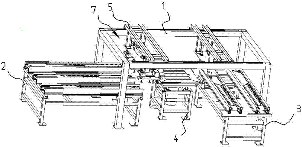
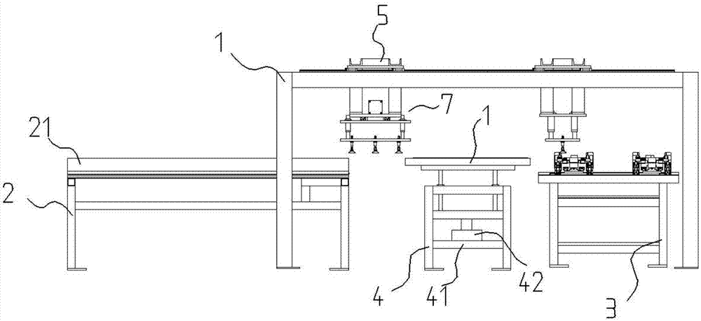
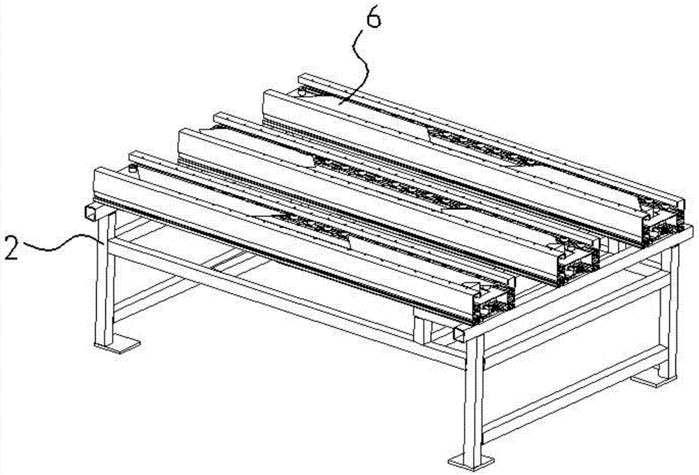
[0029] Such as Figure 1-Figure 11 As shown, the specific structure of the present invention is: a silicon steel sheet stacker, comprising a frame 1 and a stacking frame 4 arranged at the lower end of the frame 1; The horizontally moving sliding table 5 of the silicon steel sheet 6, the described laterally moving sliding table 5 is provided with multiple groups of grabbing devices 7, and the lower end of the grabbing device 7 is provided with a horizontal conveying platform 2 and a longitudinal conveying platform 3; Three parallel conveying brackets 21 are arranged on the horizontal conveying stand 2 ...


PUM


Abstract

The invention discloses a silicon steel sheet stacking machine which comprises a framework and a stacking frame. The stacking frame is arranged at the lower end of the framework; two groups of transverse movable slide tables for stacking silicon steel sheets are slidably arranged on the framework, a plurality of groups of grabbing devices are arranged on the transverse movable slide tables, and a transverse conveying rack and a longitudinal conveying rack are arranged at the lower ends of the grabbing devices; three conveying supports which are parallel to one another are arranged on the transverse conveying rack, and two conveying supports which are parallel to each other are arranged on the longitudinal conveying rack; conveying elements and pushing assemblies are arranged on the conveying supports, the conveying elements are used for driving the silicon steel sheets to move, and the silicon steel sheets can be dislocated by the pushing assemblies; a bottom plate is arranged on the stacking frame, a hydraulic cylinder is arranged on the bottom plate and is provided with a lifting plate, and upright columns are arranged on the lifting plate, penetrate fixing seats arranged on the stacking frame and are connected with a worktable. The silicon steel sheet stacking machine has the advantages that the silicon steel sheet stacking machine is simple in structure and high in production efficiency, and the silicon steel sheets can be dislocated and overlaid by the silicon steel sheet stacking machine.

Description

technical field [0001] The invention relates to the technical field of silicon steel sheet production and processing, in particular to a silicon steel sheet stacker. Background technique [0002] In the prior art, the processed silicon steel sheets need to be assembled, such as Figure 11 As shown, the upper yoke piece 61, the lower yoke piece 62, the left yoke piece 63, the right yoke piece 64, and the middle yoke piece 65 are all manually stacked according to the diagram, and the silicon steel stacked next time is deliberately stacked. The sheet does not coincide with the silicon steel sheet stacked last time. Figure 10 , in order to improve its performance, although there is a stacking device for silicon steel sheets at present, the existing stacking device cannot realize the dislocation and stacking of silicon steel sheets when stacking, so the current manufacturers still use manual stacking. Low, low degree of automation. Contents of the invention [0003] The obje...

Claims


Application Information

Patent Timeline
IPC IPC(8): B65G57/03B65G57/04B65G57/10B65G61/00
CPCB65G57/035B65G57/04B65G57/10B65G61/00B65G2201/022
Inventor 周胜强
Owner 湖南锐科机器人技术有限公司
Learn More