
Novel industrial dust removing device

A dust removal device, industrial technology, applied in the direction of cleaning methods using tools, static electricity, electrical components, etc., can solve the problems of large size, damage, inconvenient cleaning, etc., and achieve the effect of small size

Inactive Publication Date: 2017-12-08
LIANGXI HAOXING IND DESIGN OFFICE
View PDF0 Cites 5 Cited by
  • Summary
  • Abstract
  • Description
  • Claims
  • Application Information

AI Technical Summary

Problems solved by technology

[0002] Today's industrial development has driven regional economic development, but at the same time it has also brought irreversible damage to the environment. Although the environmental protection department is also urgently formulating solutions, the results are minimal. Everyone knows the importance of the environment. Our work If the environment is very bad, working for a long time will bring immeasurable damage to our body. In addition, industrial production-related equipment will also generate a lot of dust when it is in operation, which not only enters the respiratory tract with the breathing of workers, but also Part of it floats in the air, and some dust falls on the surface of industrial processing equipment, so it must be cleaned up in time. Today's dust removal equipment is basically large in size, or it is dragged on the ground, but for corners or industrial The dust at the corner of the equipment is inconvenient to clean. In addition, after the industrial equipment has been working for a long time, a certain amount of static electricity will be generated, which has a great impact on the equipment. Therefore, a new type of industrial dust removal device is designed and produced here to facilitate multiple Single use, small size, easy to handle

Method used


Image

  • Novel industrial dust removing device
  • Novel industrial dust removing device
  • Novel industrial dust removing device

Examples


Embodiment Construction

[0015] The following will clearly and completely describe the technical solutions in the embodiments of the present invention with reference to the accompanying drawings in the embodiments of the present invention. Obviously, the described embodiments are only some, not all, embodiments of the present invention. Based on the embodiments of the present invention, all other embodiments obtained by persons of ordinary skill in the art without making creative efforts belong to the protection scope of the present invention.

[0016] In the description of the present invention, it should be noted that the orientation or positional relationship indicated by the terms "vertical", "upper", "lower" and "horizontal" are based on the orientation or positional relationship shown in the drawings, and are only for It is convenient to describe the present invention and simplify the description, but does not indicate or imply that the device or element referred to must have a specific orientati...


PUM


Abstract

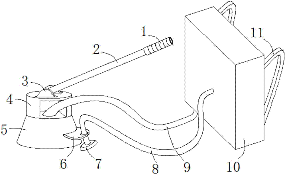
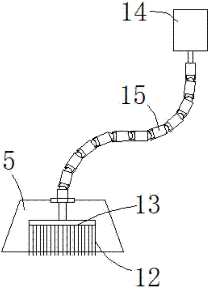
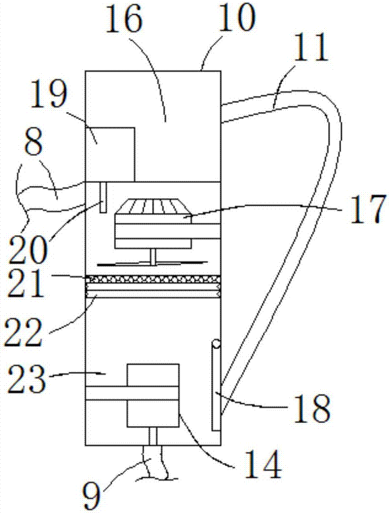
The invention discloses a novel industrial dust removing device. The novel industrial dust removing device comprises a control box and a dust suction hood. The control box comprises a control chamber and an air suction chamber. The bottom end face of the air suction chamber communicates with a first air guide tube; a driving motor is fixedly mounted at the bottom end of an inner cavity of the air suction chamber through a fixing rack; an air suction fan is fixedly mounted at the top of the inner cavity of the air suction chamber through a fixing rack; the left end face of the top of the air suction chamber communicates with a second air guide tube; a high pressure generator is fixedly mounted at the left end of an inner cavity of the control chamber; an ionic wind rod is fixedly mounted on the left side of the top end of the inner cavity of the air suction chamber in the vertical direction; the driving motor is connected with a universal coupling through a power shaft; the top end of the dust suction hood communicates with the first air guide tube; a rotary disc is rotationally connected to the top end face of an inner cavity of the dust suction hood in an inserting mode; and the universal coupling penetrates through the top end face of the dust suction hood and is fixedly connected with top end face of the rotary disc. By means of the novel industrial dust removing device, dust on industrial equipment can be conveniently cleaned up and collected, and static electricity on the equipment can be eliminated.

Description

technical field [0001] The invention relates to the technical field of industrial dust removal application, in particular to a novel industrial dust removal device. Background technique [0002] Today's industrial development has driven regional economic development, but at the same time it has also brought irreversible damage to the environment. Although the environmental protection department is also urgently formulating solutions, the results are minimal. Everyone knows the importance of the environment. Our work If the environment is very bad, working for a long time will bring immeasurable damage to our body. In addition, industrial production-related equipment will also generate a lot of dust when it is in operation, which not only enters the respiratory tract with the breathing of workers, but also Part of it floats in the air, and some dust falls on the surface of industrial processing equipment, so it must be cleaned up in time. Today's dust removal equipment is bas...

Claims


Application Information

Patent Timeline
IPC IPC(8): B08B1/04B08B5/04B01D46/12H05F3/06
CPCB01D46/12H05F3/06B08B5/04B08B1/12B08B1/32
Inventor 刘爱珍
Owner LIANGXI HAOXING IND DESIGN OFFICE
Learn More