
Telescopic sprayer for mortar spraying machine and capable of controlling flow

A technology for controlling the flow rate and spraying machine, which is applied in the direction of spraying device, spraying device, wellbore lining, etc., which can solve the problems of lower working efficiency, uncertain wall position, and slurry leakage, so as to improve the use effect, facilitate effective use, and improve The effect of work efficiency

Inactive Publication Date: 2017-12-08
赵杭森
View PDF0 Cites 6 Cited by
  • Summary
  • Abstract
  • Description
  • Claims
  • Application Information

AI Technical Summary

Problems solved by technology

[0003] Generally, the flow rate of the nozzle of the spraying machine is fixed. When the sprayed wall of the building is too large, the flow rate of the nozzle is small, which will increase the labor intensity of the construction personnel and is not conducive to improving work efficiency; when the sprayed wall of the building is small, The flow rate of the nozzle is relatively large, which will spray onto other buildings, causing pollution and other effects, and affecting the construction effect; and during the construction process, the position of the wall is not fixed, and the length of the conduit connected to the nozzle is generally fixed, and the feeder can be moved as needed, which will reduce work Efficiency, which is not conducive to the effective use of the shotcrete machine; and it is easy to fall off at the connecting end of the connecting extension pipe, and it is easy to cause the grout to leak

Method used


Image

  • Telescopic sprayer for mortar spraying machine and capable of controlling flow
  • Telescopic sprayer for mortar spraying machine and capable of controlling flow
  • Telescopic sprayer for mortar spraying machine and capable of controlling flow

Examples


Embodiment Construction

[0020] The following will clearly and completely describe the technical solutions in the embodiments of the present invention with reference to the accompanying drawings in the embodiments of the present invention. Obviously, the described embodiments are only some, not all, embodiments of the present invention. Based on the embodiments of the present invention, all other embodiments obtained by persons of ordinary skill in the art without making creative efforts belong to the protection scope of the present invention.

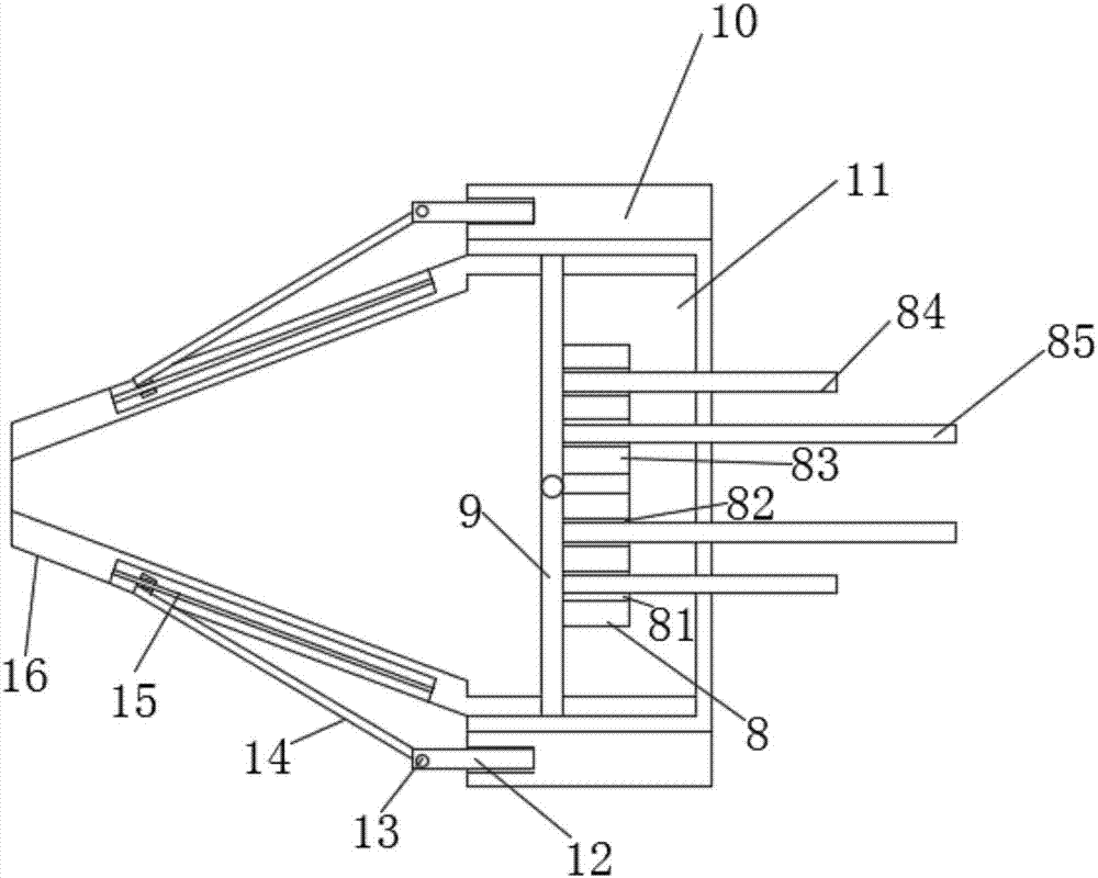
[0021] see Figure 1-5 , the present invention provides a technical solution: a telescopic nozzle for spraying machine with controllable flow rate, comprising an outer conduit 1, an inner conduit 2 and a nozzle 16, the outer conduit 1 is provided with an inner conduit 2, and the inner conduit 2 is fixed The first ferrule 3 is sleeved, and the first ferrule 3 is composed of a bottom ring, an inner ring sleeve and an outer ring sleeve. Ball grooves are provided ...


PUM


Abstract

The invention discloses a telescopic sprinkler head for a spraying machine with controllable flow rate, which comprises an outer conduit, an inner conduit and a sprinkler head, the outer conduit is provided with an inner conduit, and a first ferrule is fixedly sleeved on the inner conduit , the inner end of the inner catheter is provided with a catheter chuck, and the catheter chuck and one side of the first ferrule are engaged with each other, the two sides of the first ferrule are provided with spring grooves, and the inner walls of the two spring grooves are respectively fixed The first spring is connected, and the end of the inner conduit away from the first ferrule is slidably sleeved with the second ferrule. In the present invention, an inner conduit is arranged in the outer conduit, and a filter plate is arranged on the inner conduit, and three filter ports are arranged on the filter plate, and a disc seat is provided on the spray head device detachably threaded with the inner conduit, and three filter ports are arranged on the disc seat. There are two slots, and two plugs are plugged into the disc seat, and the flow rate through the filter port is controlled by moving the nozzle device to control the flow rate of the nozzle, so as to meet the spraying requirements of different walls and improve the use of the spraying machine. Effect.

Description

technical field [0001] The invention relates to the field of construction equipment, in particular to a telescopic sprinkler head for a spraying machine that can control the flow rate. Background technique [0002] The spraying machine is a new type of high-efficiency spraying machine, which is mainly suitable for the concrete spraying operation of the roadway with a section of 5m*5m. The equipment uses a concrete pump to transport the concrete to the nozzle of the manipulator through the pipeline, and uses the compressed air with the accelerator to spray the concrete to the wall of the sprayed roadway. It has reasonable structure, humanized design, reliable performance, convenient operation and maintenance, and long service life. Dust-free, low noise and low rebound rate during work. This machine greatly reduces the dust concentration near the machine and at the nozzle, improves the working environment of workers, and reduces the pneumoconiosis caused by excessive dust. ...

Claims


Application Information

Patent Timeline
IPC IPC(8): B05B1/30B05B1/14B05B13/02B05B15/06E21D11/10
CPCB05B1/3033B05B1/14B05B13/0278B05B15/628E21D11/105
Inventor 赵杭森
Owner 赵杭森
Learn More