A circulating fluidized bed external heat exchanger to improve the heat transfer uniformity of gas-solid flow
A circulating fluidized bed, external technology, applied in fluidized bed heat exchangers, indirect heat exchangers, heat exchanger types, etc., can solve the problem of uneven gas-solid fluidization of external heat exchangers, and achieve The effect of reducing the cost of consumables, eliminating gas-solid stagnation zones, and improving uniformity
- Summary
- Abstract
- Description
- Claims
- Application Information
AI Technical Summary
Problems solved by technology
Method used
Image
Examples
Embodiment 1
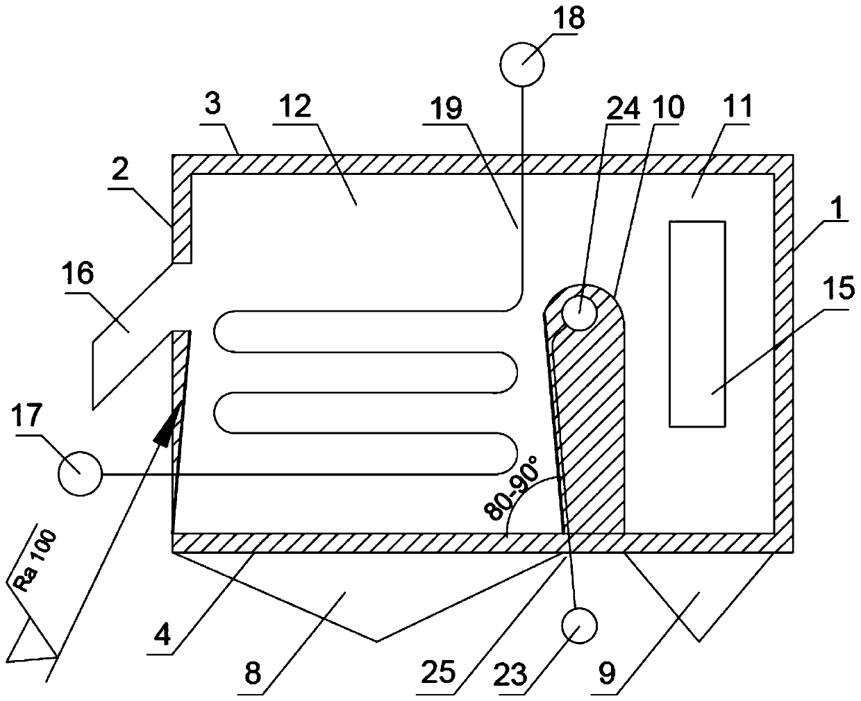
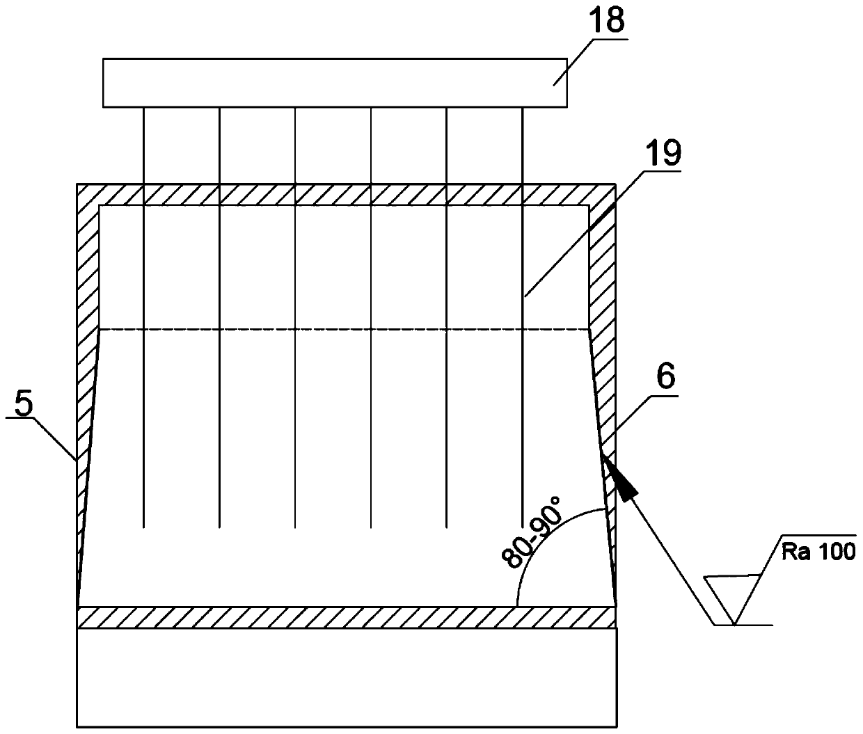
[0028] like figure 1 , figure 2 As shown, a circulating fluidized bed external heat exchanger for improving gas-solid flow and gas-solid heat exchange uniformity described in this embodiment includes a front wall 1, a rear wall 2, a top plate 3, a bottom air distribution plate 4, a left Side wall 5, right side wall 6, air chamber 8 of cooling chamber A, air chamber 9 of mixing chamber, partition wall A 10, mixing chamber 11, cooling chamber A 12, circulating ash inlet 15, circulating ash outlet 16, inlet steam Header A 17, outlet steam header A 18, heating surface tube panel A 19, inlet steam header 23 in partition wall A, outlet steam header 24 in partition wall A, membrane wall 25 in partition wall A.
[0029] The front wall 1, the rear wall 2, the top plate 3, the bottom air distribution plate 4, the left side wall 5, the right side wall 6 and the partition wall A 10 are made of refractory materials. The partition wall A 10 divides the external heat exchanger into a mixi...
Embodiment 2
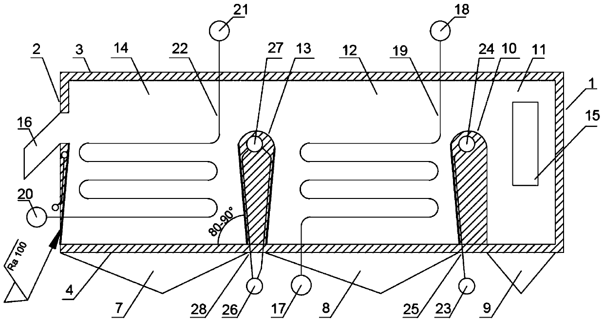
[0033] like image 3 , Figure 4As shown, the fluidized bed external heat exchanger of this embodiment includes a front wall 1, a rear wall 2, a top plate 3, a bottom air distribution plate 4, a left wall 5, a right wall 6, and an air chamber 7 of the cooling chamber B. , Air chamber 8 of cooling chamber A, air chamber 9 of mixing chamber, partition wall A 10, mixing chamber 11, cooling chamber A 12, partition wall B 13, cooling chamber B 14, circulating ash inlet 15, circulating ash outlet 16, Inlet steam header A 17, outlet steam header A 18, heating surface tube panel A 19, inlet steam header B 20, outlet steam header B 21, heating surface tube panel B 22, inlet steam header in partition wall A Box 23, outlet steam header in partition A 24, membrane wall of partition A 25, inlet steam header in partition B 26, outlet steam header in partition B 27, membrane of partition B Type wall 28, inlet steam header 29 in the right wall, outlet steam header 30 in the right wall, memb...
Embodiment 3
[0039] like Figure 5 , Figure 6 As shown, the fluidized bed external heat exchanger of this embodiment includes a front wall 1, a rear wall 2, a top plate 3, a bottom air distribution plate 4, a left wall 5, a right wall 6, and an air chamber 8 of the cooling chamber A. , Air chamber 9 of mixing bin, partition wall A 10, mixing bin 11, cooling bin A 12, circulating ash inlet 15, circulating ash outlet 16, inlet steam header A 17, outlet steam header A 18, heating surface tube panel A19, inlet steam header 23 in partition wall A, outlet steam header 24 in partition wall A, membrane wall 25 of partition wall A, rear wall steam header I 35, rear wall steam header II 36.
[0040] The front wall 1, rear wall 2, top plate 3, bottom air distribution plate 4, left side wall 5 and right side wall 6 of the external heat exchanger adopt a membrane wall structure, and the diameter of the membrane wall tube is The range is 28-76mm; the membrane walls of the front wall 1 and the rear w...
PUM
 Abstract
Description
Claims
Application Information
 - R&D
- Intellectual Property
- Life Sciences
- Materials
- Tech Scout
- Unparalleled Data Quality
- Higher Quality Content
- 60% Fewer Hallucinations
Browse by: Latest US Patents, China's latest patents, Technical Efficacy Thesaurus, Application Domain, Technology Topic, Popular Technical Reports.
© 2025 PatSnap. All rights reserved.Legal|Privacy policy|Modern Slavery Act Transparency Statement|Sitemap|About US| Contact US: help@patsnap.com


