Film synchronous embossing device

A technology of embossing and thin film, which is applied in the field of synchronous embossing device for thin film, which can solve the problems of long materials, waste, and the need for multiple tests to meet the requirements, etc.

Pending Publication Date: 2017-12-05
FOSHAN PUYING MACHINERY EQUIP
View PDF4 Cites 4 Cited by
  • Summary
  • Abstract
  • Description
  • Claims
  • Application Information

AI Technical Summary

Problems solved by technology

However, in the existing film embossing devices, a single motor is used to drive the embossing roller to rotate, and the rubber roller is passively operated to realize the embossing of the film. One of the biggest disadvantages of this design is that if the printed pattern and embossing The lines of the rollers are not aligned. When adjustments are needed, the printing speed of the printing roller must be accelerated or slowed down. There is a long distance between the printing roller and the embossing roller, so the speed of the two must be consistent. , during the adjustment period, a very long amount of materi...

Method used


Image

  • Film synchronous embossing device
  • Film synchronous embossing device
  • Film synchronous embossing device

Examples


Embodiment 1

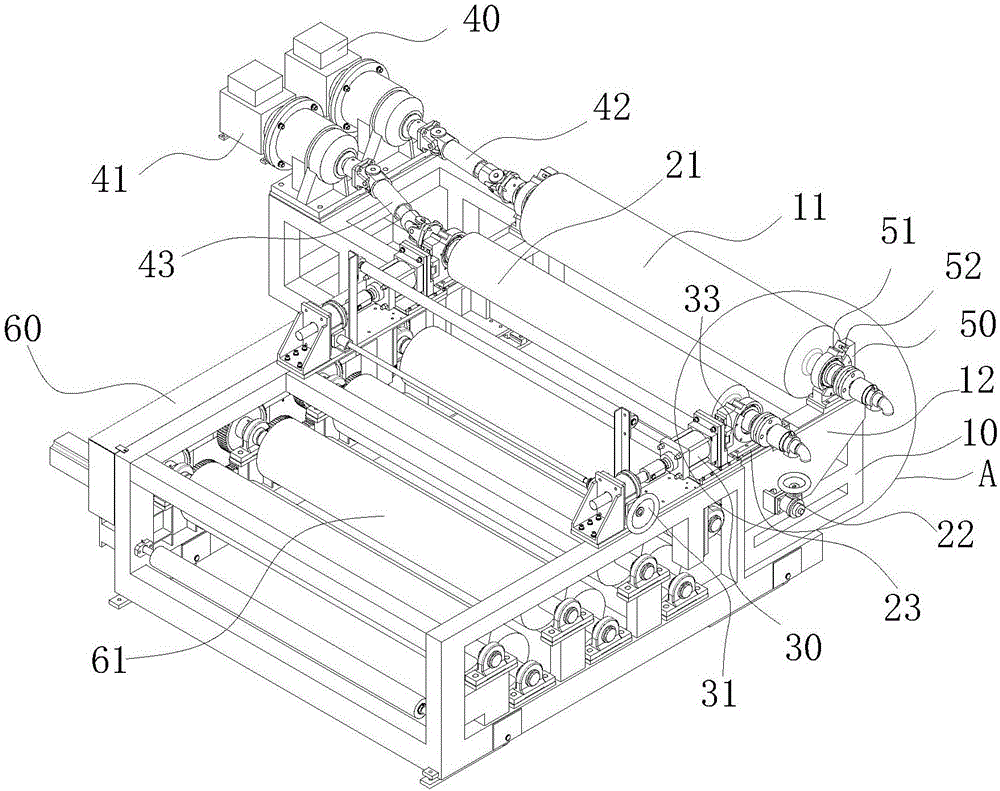
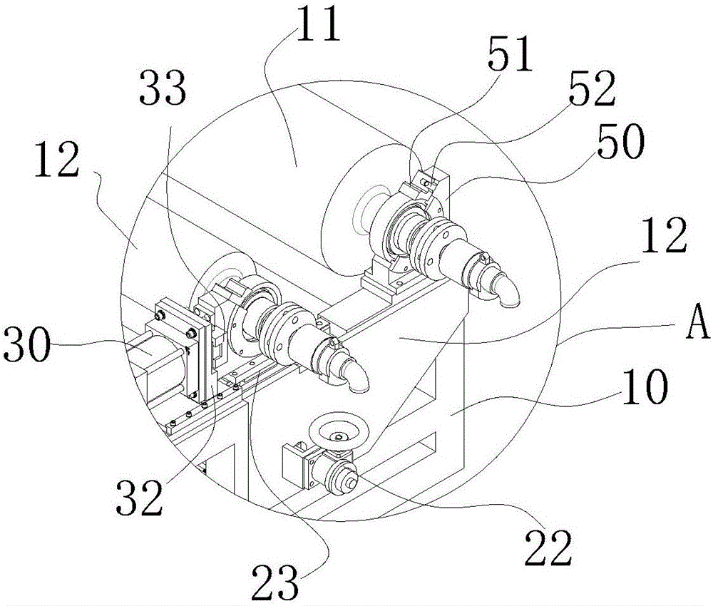
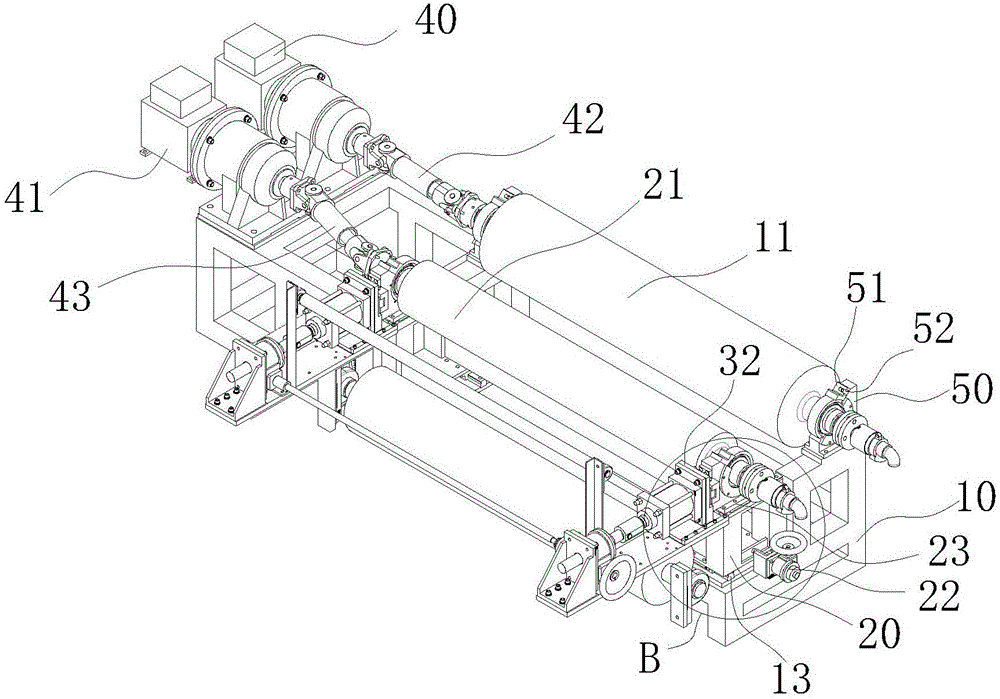
[0021] like Figure 1-5 As shown, a synchronous embossing device for a film in this embodiment includes a first support 10, a rubber roller 11 arranged on the first support 10, a second support 20, and an embossing roller arranged on the second support 20 21. The surface of the embossing roller 21 is provided with the same uneven texture as the film pattern, the rubber roller 11 and the embossing roller 21 are respectively connected to the first motor 40 and the second motor 41, the first motor 40 and the The second motor 41 independently controls the rotation direction and speed of the rubber roller 11 and the embossing roller 21 respectively, and the embossing roller 21 can move relative to the rubber roller 11 in four directions, front, rear, left, and right on the horizontal plane. In the traditional embossing device, the embossing roller adopts the active transmission method, while the rubber roller adopts the passive transmission method. It is necessary to adjust the cor...

Embodiment 2

[0023] like Figure 1-5 As shown, the rubber roller 11 is connected to the first motor 40 through the first universal coupling 42 , and the embossing roller 21 is connected to the second motor 41 through the second universal coupling 43 . The distance between the embossing roller 21 and the rubber roller 11 needs to be adjusted back and forth, and the position of the second motor 41 is fixed, so the distance between the second motor 41 and the embossing roller 21 will have a certain change. The universal coupling 43 is scalable, so that the second motor 41 can control the rotation direction and rotation speed of the embossing roller 21 without changing the position of the second motor 41 . In order to meet wider requirements for the synchronous embossing device of this embodiment, the first telescopic rod 42 is also set in this way.

Embodiment 3

[0025] like Figure 1-5 As shown, in this embodiment, the structural device for the embossing roller 21 to move left and right relative to the rubber roller 11 is perfected. The rubber roller 11 is fixed on the first bracket 10 through the fixing seat 50, the embossing roller 21 is arranged on the second bracket 20, and the first bracket 10 is provided with a left and right moving slide rail 13, so The second support 20 described above is connected to the first support 10 through the left and right moving slide rails 13, and the first support 10 can slide on the left and right moving slide rails 13 to adjust the left and right relative positions of the embossing roller 21 and the rubber roller 11. Since the embossing roller 21 is arranged on the second support 20, and the rubber roller 11 is fixed on the first support 10, it is only necessary to adjust the left and right positions between the first support 10 and the second space 20, and the The purpose of adjusting the left ...


PUM


Abstract

The invention relates to the field of film synchronous embossing and particularly relates to a film synchronous embossing device. The device comprises a first bracket, a rubber roller arranged on the first bracket, a second bracket and an embossing roller arranged on the second bracket. The surface of the embossing roller is provided with uneven patterns the same to the film patterns. The rubber roller and the embossing roller are respectively connected to a first motor and a second motor. The first motor and the second motor respectively control a rotation direction and a rotation rate of the rubber roller and the embossing roller. The embossing roller can move relative to the rubber roller on the plane along front, rear, left and right directions. The device is free of a single driven embossing roller and a passively driven rubber roller of the conventional embossing device and drives the embossing roller and the rubber roller through the different driving devices so that the relative position of the embossing roller and a film can be adjusted at an embossing position at any time and thus the embossing patterns are corresponding to the printing patterns and the adjustment of the materials having high waste in the traditional process is avoided.

Description

【Technical field】 [0001] The invention relates to the field of film synchronous embossing, in particular to a film synchronous embossing device. 【Background technique】 [0002] The embossing process is a process that uses a concave-convex mold to plastically deform the printed matter under a certain pressure, thereby artistically processing the surface of the printed matter. Usually the product is printed and embossed simultaneously to ensure a one-to-one correspondence between the printed pattern and the embossed pattern. However, in the existing film embossing devices, a single motor is used to drive the embossing roller to rotate, and the rubber roller is passively operated to realize the embossing of the film. One of the biggest disadvantages of this design is that if the printed pattern and embossing The lines of the rollers are not aligned. When adjustments are needed, the printing speed of the printing roller must be accelerated or slowed down. There is a long distan...

Claims


Application Information

Patent Timeline
IPC IPC(8): B29C59/04
CPCB29C59/04
Inventor 龚卫坚陈冠棣
Owner FOSHAN PUYING MACHINERY EQUIP
Why Eureka
Try Eureka