Reaction vessel multi-shaft stirring device

A stirring device and reactor technology, which is applied in mixers with rotating stirring devices, chemical/physical/physical chemical fixed reactors, transportation and packaging, etc., can solve the problems of inconvenient use, difficult discharge of crystals, and uneven reaction And other issues

Inactive Publication Date: 2017-12-05
WUHU YIZE SMALL & MEDIUM ENTERPRISE PUBLIC SERVICE CO LTD
View PDF0 Cites 6 Cited by
  • Summary
  • Abstract
  • Description
  • Claims
  • Application Information

AI Technical Summary

Problems solved by technology

Stirring devices in the prior art generally include a stirring shaft, and a stirring paddle convenient for stirring is installed at the lower end of the stirring shaft. The single shaft stirring device, because there is only one stirring shaft, the reaction solution at the edge of the reactor cannot be stirred, so The stirring effect is poor. For the reaction with crystallization, the crystallization will often crystallize and fix on the inner wall of the reactor, resulting in uneven reaction and difficult discharge of crystallization, so it is very inconvenient to use; in addition, the stirring blade at the lower end of the stirring shaft will Under the downward gravity of the fluid, the stirring shaft will be subject to a large axial force

Method used


Image

  • Reaction vessel multi-shaft stirring device
  • Reaction vessel multi-shaft stirring device

Examples


Embodiment 1

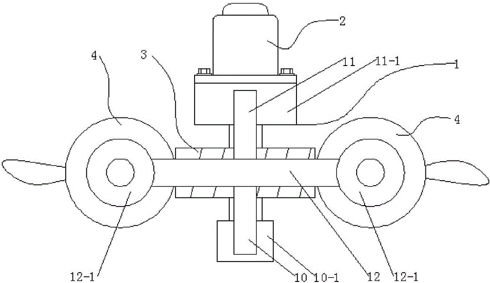
[0025] In this reaction kettle multi-axis stirring device, one end of the central shaft of the helical gear-3 is connected to the output shaft of the motor 2, and the other end is connected to the bearing seat-10-1 through a rolling bearing, so the motor 2 drives the helical gear-3 through the output shaft Rotate counterclockwise, because the first helical gear 3 meshes with the second helical gear 4, so the two helical gears 4 move relative to each other, and the two stirring shafts 5 also rotate relatively, and then the driven stirring blade 50 also moves relatively, so that The reaction liquid in the reaction kettle is mixed more evenly. In addition, the stirring blades 50 are double-rotating blades, and the stirring blades 50 driven by the double stirring shafts 5 rotate relatively, which improves the stirring effect.

[0026] The stirring seat 1 is cross-shaped, which ensures the stability of the meshing of the first helical gear 3 and the second helical gear 4 .

Embodiment 2

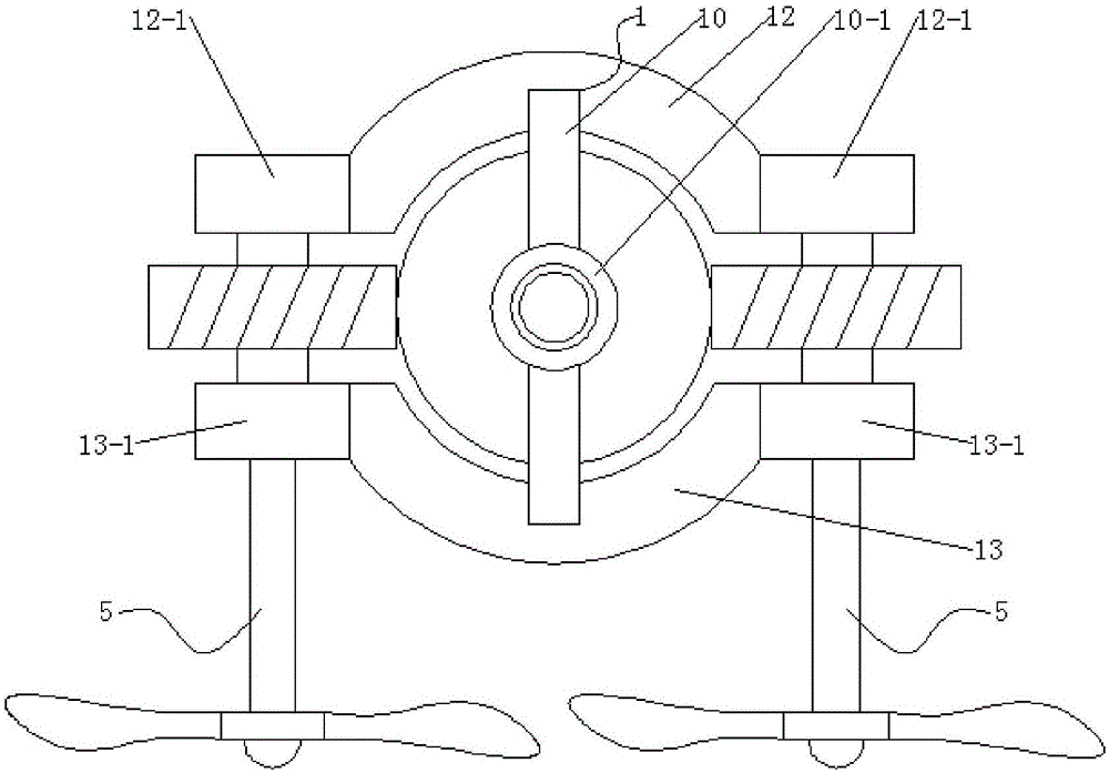
[0028] The upper end of the stirring shaft 5 is respectively connected with the bearing seat 3 12-1 and the bearing seat 4 13-1 through rolling bearings, and the stirring shaft 5 and the bearing seat 12-1 are installed and the stirring shaft 5 and the bearing seat are installed. The rolling bearing of four 13-1 adopts tapered roller bearings, and the axial stress strength of stirring shaft 5 is ensured by adopting bearing housing three 12-1 and bearing housing four 13-1 to fix the stirring shaft 5 and connecting with tapered roller bearings .


PUM


Abstract

The invention discloses a reaction vessel multi-shaft stirring device. The reaction vessel multi-shaft stirring device comprises a stirring seat, a motor, a helical gear 1, a helical gear 2, and mixer shafts; the stirring seat is composed of a front half seat, a rear half seat, an upper half seat and a lower half seat, a bearing pedestal 1 is arranged at the front end of the front half seat, a bearing pedestal 2 is arranged at the rear end of the rear half seat, a bearing pedestal 3 is arranged at two ends of the upper half seat, a bearing pedestal 4 is arranged at two ends of the lower half seat, the motor is connected with a transverse plane of the bearing pedestal 2, one end of a center shaft of the helical gear 1 is connected with an output shaft of the motor, the other end is connected with the bearing pedestal 1 through a rolling bearing, the upper ends of the mixer shafts are respectively connected with the bearing pedestal 3 and the bearing pedestal 4 through the rolling bearings, the helical gear 2 is arranged between the bearing pedestal 3 and the bearing pedestal 4, and is connected with the mixer shaft, the helical gear 1 and the helical gear 2 are engaged, the stirring blades driven by double mixer shafts are relatively rotated, the stirring effect is increased, the double bearing pedestals are employed for fixing the mixer shafts, and the tapered rolling bearing is employed, so that the axial bearing intensity of the mixer shafts can be guaranteed.

Description

technical field [0001] The invention belongs to the technical field of stirring devices, in particular, the invention relates to a multi-shaft stirring device for a reaction kettle. Background technique [0002] In many fields such as chemical industry, pharmacy and testing, it is inevitable to use the reactor. A stirring device is installed in the reactor to stir the reaction liquid in the reactor so that the reaction liquid in the reactor can be mixed evenly. Guaranteed responsiveness. Stirring devices in the prior art generally include a stirring shaft, and a stirring paddle convenient for stirring is installed at the lower end of the stirring shaft. The single shaft stirring device, because there is only one stirring shaft, the reaction solution at the edge of the reactor cannot be stirred, so The stirring effect is poor. For the reaction with crystallization, the crystallization will often crystallize and fix on the inner wall of the reactor, resulting in uneven reacti...

Claims


Application Information

Patent Timeline
Patent Type & Authority Applications(China)
IPC IPC(8): B01J19/18B01F7/16
CPCB01J19/0066B01J19/18B01F27/21B01F27/2322B01F27/85B01F2101/2204
Inventor 高涵
Owner WUHU YIZE SMALL & MEDIUM ENTERPRISE PUBLIC SERVICE CO LTD
Why Eureka
Try Eureka