Diffusion plate
A diffusion plate and diffusion characteristic technology, applied in the field of diffusion plate, can solve the problems of uneven color, uneven brightness, etc., and achieve the effect of less uneven color, less uneven brightness, and simple structure
- Summary
- Abstract
- Description
- Claims
- Application Information
AI Technical Summary
Problems solved by technology
Method used
Image


Examples
Embodiment approach 1
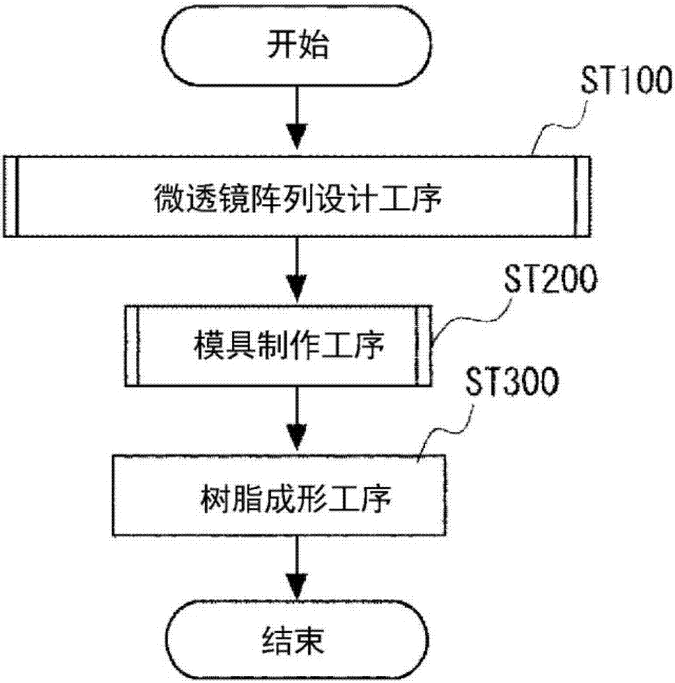
[0046] Hereinafter, embodiments of the present invention will be described with reference to the drawings.
[0047] (shape of diffuser plate)
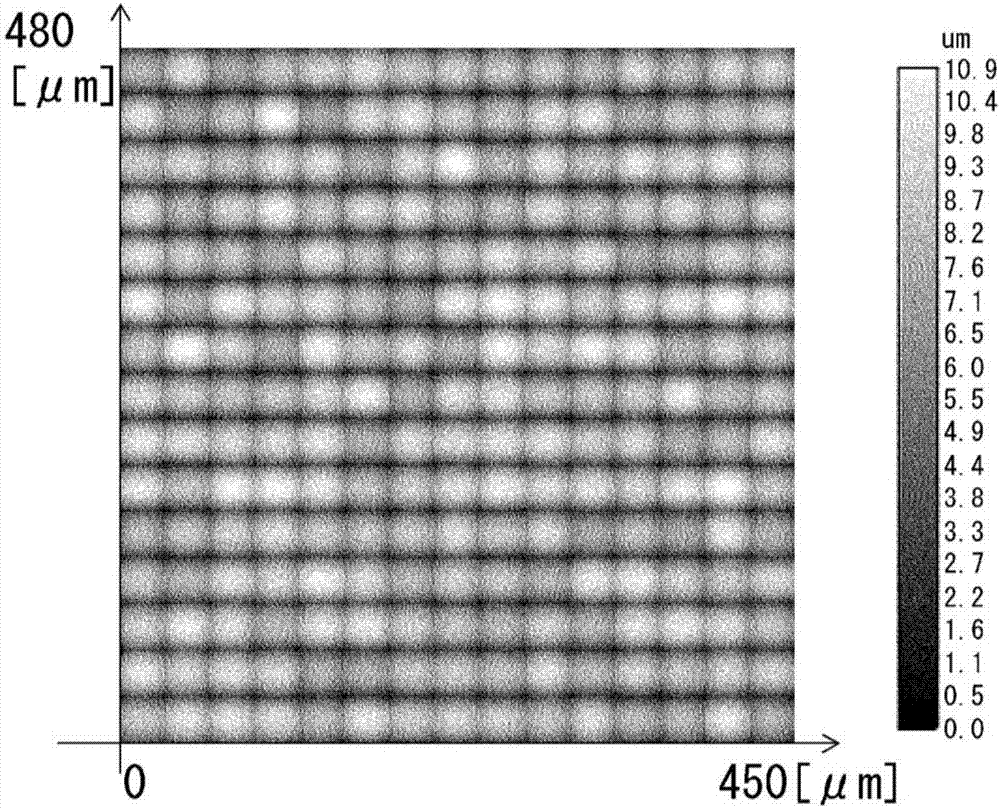
[0048] figure 1 It is a figure which shows the cross-sectional profile of the diffuser plate 1 of this embodiment in the cross-section perpendicular|vertical to the main surface S1. like figure 1As shown, the diffusion plate 1 is a light diffusion plate in which a plurality of microlenses 2 are arranged on the main surface S1 of the substrate. The plurality of microlenses 2 are arranged in a grid on the principal surface S1. figure 1 The vertical axis of represents the height of the main surface S1 of the lens shape with the height of the main surface S1 of the substrate being 0. figure 1 The horizontal axis of represents the position parallel to the direction of the main surface S1. Moreover, the optical axis of the microlens array which consists of several microlenses 2 faces the direction perpendicular to main surface S1. ...
Embodiment
[0115] Hereinafter, based on the example of the diffuser plate 1 of this embodiment, this invention is demonstrated in more detail.
[0116] In the diffuser plate 1 of this embodiment, as described above, the microlens array including the plurality of microlenses 2 on the main surface S1 is designed by dividing the phase modulation shape 4 and the plurality of reference microlenses 3 .
[0117] Across the entire microlens array, a phase modulation shape 4 is set. In the phase modulation shape 4, the maximum height difference from the main surface S1 for imparting a phase difference is ΔH=1.5 μm. On the main surface S1, uniform random numbers corresponding to the respective positions of the plurality of microlenses 2 are generated, and a raised height (raised portion) for imparting a phase difference is set. However, when a different raised height is set only for each microlens 2 among the plurality of microlenses 2 , the phase difference between adjacent microlenses 2 becomes...
PUM
| Property | Measurement | Unit |
|---|---|---|
| diameter | aaaaa | aaaaa |
| radius | aaaaa | aaaaa |
| refractive index | aaaaa | aaaaa |
Abstract
Description
Claims
Application Information
 - Generate Ideas
- Intellectual Property
- Life Sciences
- Materials
- Tech Scout
- Unparalleled Data Quality
- Higher Quality Content
- 60% Fewer Hallucinations
Browse by: Latest US Patents, China's latest patents, Technical Efficacy Thesaurus, Application Domain, Technology Topic, Popular Technical Reports.
© 2025 PatSnap. All rights reserved.Legal|Privacy policy|Modern Slavery Act Transparency Statement|Sitemap|About US| Contact US: help@patsnap.com