Transmission control device and transmission control method

A technology of control devices, control methods, applied in the direction of transmission control, elements with teeth, belts/chains/gears, etc.

Active Publication Date: 2017-12-01
JATCO LTD +1
View PDF7 Cites 0 Cited by
  • Summary
  • Abstract
  • Description
  • Claims
  • Application Information

AI Technical Summary

Problems solved by technology

Therefore, in this technique, the action of t

Method used


Image

  • Transmission control device and transmission control method
  • Transmission control device and transmission control method
  • Transmission control device and transmission control method

Examples


Embodiment Construction

[0017] Hereinafter, embodiments of the present invention will be described with reference to the drawings.

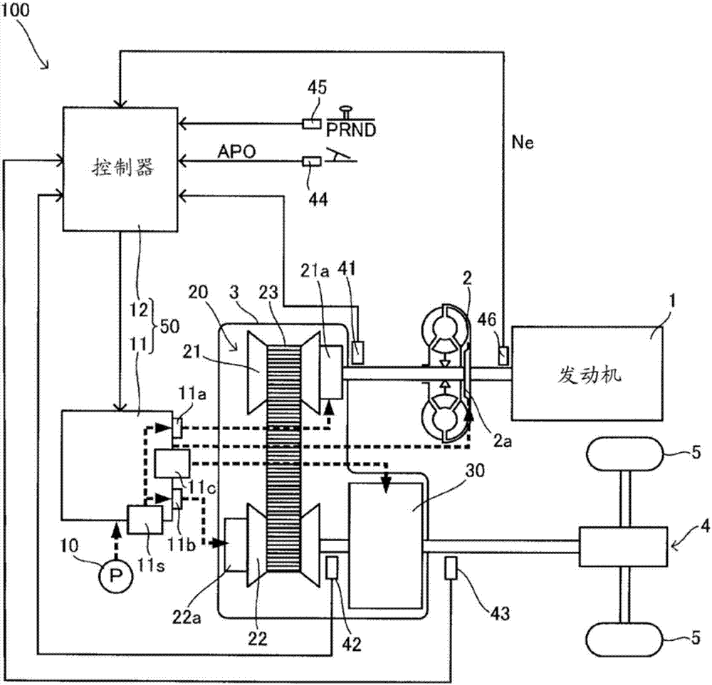
[0018] figure 1 It is a figure which shows the main part of the vehicle including the transmission 100. The vehicle includes an engine 1 , a torque converter 2 , a transmission mechanism 20 , an auxiliary transmission mechanism 30 , an axle 4 , and drive wheels 5 .

[0019] The engine 1 constitutes a power source of the vehicle. The torque converter 2 transmits power via fluid. In the torque converter 2, power transmission efficiency can be improved by engaging the lock-up clutch 2a. The transmission mechanism 20 and the subtransmission mechanism 30 output the input rotation speed at a rotation speed corresponding to the transmission ratio. The gear ratio is a value obtained by dividing the input rotation speed by the output rotation speed. The axle 4 is a drive axle constituted by a reduction gear or a differential. The motive power of the engine 1 is transmitted...


PUM


Abstract

The present invention pertains to a transmission control device that is provided with a controller (12) and an oil pressure control circuit (11). The controller (12) determines whether a rotation sensor (42) has failed. The controller (12) and the oil pressure control circuit (11) variably control the gear ratio of a variator (20) and variably control the gear speed of an auxiliary transmission mechanism (30). If it is determined that a failure has occurred, the controller (12) and the oil pressure control circuit (11) fix the gear speed of the auxiliary transmission mechanism (30) at a first speed. If the gear speed of the auxiliary transmission mechanism (30) is a second speed when it is determined that a failure has occurred, the controller (12) and the oil pressure control circuit (11) fix the gear speed of the auxiliary transmission mechanism (30) at the first speed when the vehicle is stopped.

Description

technical field [0001] The invention relates to a control device of a transmission and a control method of the transmission. Background technique [0002] JP5-46465B discloses a technique for ensuring safety at the time of failure of the rotational speed sensor of the secondary pulley of the continuously variable transmission. In this technology, when the rotation speed sensor of the secondary pulley fails, the gear ratio is fixed at the maximum gear ratio, that is, the lowest gear ratio, thereby ensuring the startability of the vehicle. [0003] In the technique of JP5-46465B, a transmission mechanism including a primary pulley, a secondary pulley, and a belt has a function of ensuring vehicle startability. Therefore, in this technique, the operation of the transmission mechanism after a failure is fixed. Contents of the invention [0004] The present invention is made in view of such technical problems, and an object of the present invention is to provide a transmissio...

Claims


Application Information

Patent Timeline
IPC IPC(8): F16H61/12F16H59/40F16H61/662
CPCF16H59/40F16H61/662F16H2061/6614F16H61/702F16H2061/1284F16H2312/16F16H61/12F16H59/44F16H61/0021F16H2059/446F16H2061/1232
Inventor 大园青加滨野正宏
Owner JATCO LTD
Why Eureka
Try Eureka