
Clip

A clip and component technology, applied in the direction of frictional clamping of detachable fasteners, thin plate connection, engine sealing, etc. The effect of absorbing board thickness dimension

Active Publication Date: 2017-12-01
NIFCO INC
View PDF10 Cites 1 Cited by
  • Summary
  • Abstract
  • Description
  • Claims
  • Application Information

AI Technical Summary

Problems solved by technology

In this structure, in the case of forming the disc portion 16 having the sealing surface 18A, that is, the disc-shaped suction cup portion, as a molding die, in general parting, the sealing surface of the suction cup portion occurs at the parting line, that is, Radial steps and scars caused by the traces of the mold clamping part of the metal mold and the drawing-out traces of the slide mold may hinder water-tightness or watertightness, but this problem has been solved by improving the forming mold

Method used


Image

  • Clip
  • Clip
  • Clip

Examples


Embodiment Construction

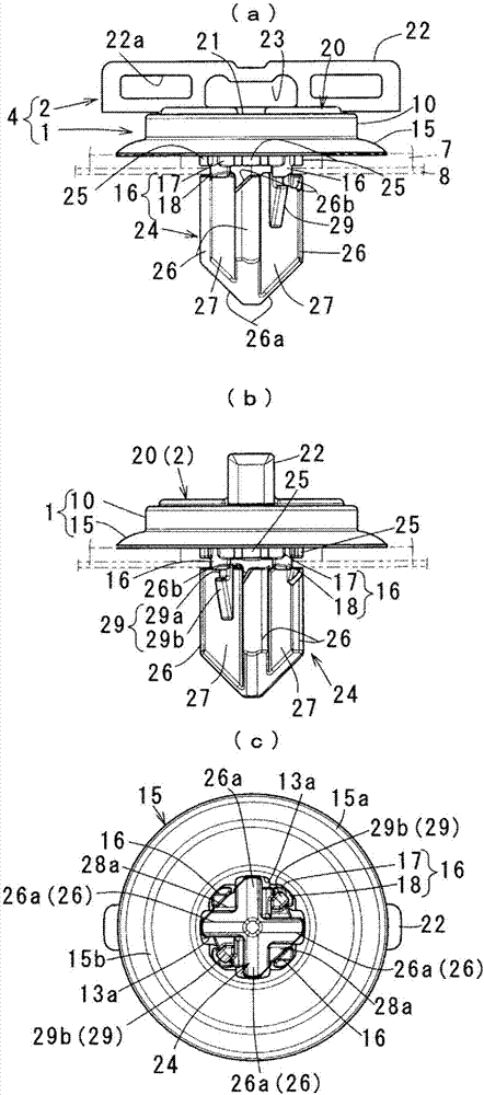
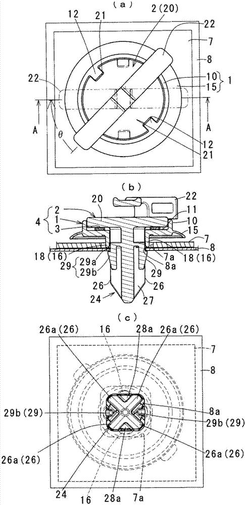
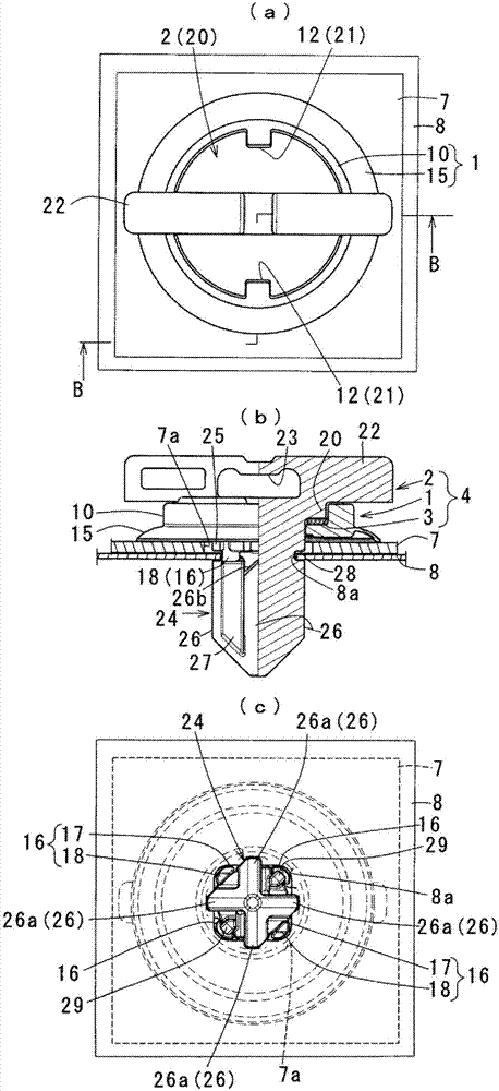
[0039] Hereinafter, embodiments and modifications of the present invention will be described with reference to the drawings. In this instruction, after describing the construction of the clip in detail, to make the assembly and main action clear, finally mentioned Figure 9 modification example.

[0040] (Structure) The clip 4 of the present embodiment is used in the case of detachably attaching one part 7 as a seal plate or the like to another part 8 such as a vehicle body or a panel, and is provided with a plug provided on the one part 7 and the other part 8 . The head 10 is arranged so as to form the through hole 7a of one member 7 among the through holes 7a, 8a of the member 8 , and the leg portion 24 is inserted into the through holes 7a, 8a and engaged with the back side of the other member 8 . That is, this clip 4 includes: a washer 1, which is a first member having a head 10, a suction cup portion 15 protruding around the head 10, and an insertion hole 13 for a leg; ...


PUM


Abstract

This clip 4 is used for, for example, attaching and constraining one member 8 to the other member 7 in a detachable manner, and is provided with a head disposed so as to block off a through hole of one of the members among through holes 8a, 7b formed through the two members, and a leg which is inserted in the through hole, and which engages the back side of the other member. The clip 4 is at least provided with a first member 1 having a head 10, a suction part 15 protruding from the circumference of the head, and an insertion hole 13 in the axial direction, and a second member 2 having a head 20 overlaid so as to have a watertight structure with the head 10 of the first member, and the leg 24 formed perpendicularly with respect to the head, and inserted in the insertion hole 13.

Description

technical field [0001] The present invention relates to a clip that is particularly suitable for a case where one member is detachably attached to the other, or the like. Background technique [0002] The clip is used when one part is detachably mounted or bound to the other part, etc., and it has: a head arranged to block the through hole of one of the through holes provided in the two parts; and a leg part, Insert it into the through hole and engage with the other side of the component. As an example, Figure 10 Indicates the clip disclosed in Patent Document 1, Figure 10 (a) is a perspective view of a single clip, Figure 10 (b) is a cross-sectional view showing both the clip and the molding die. This clip 10 is a resin molded body and includes an anchor portion 12 , a connecting portion 14 and a disc portion 16 . The anchor part 12 corresponds to the leg part of this invention, and the connection part 14 and the dish part 16 correspond to the head part of this inventi...

Claims


Application Information

Patent Timeline
Patent Type & Authority Applications(China)
IPC IPC(8): F16B19/10F16B21/04F16J15/10
CPCF16B21/04F16J15/10F16B21/086F16B19/10F16B2/20F16B5/0607F16B5/0642F16B21/02F16J15/104
Inventor 黑川拓哉
Owner NIFCO INC
Learn More