Metal formed product including tubular part having slit and manufacturing method therefor, and manufacturing device and die used for same
A technology of metal forming, manufacturing method, applied in the field of manufacturing devices and molds
- Summary
- Abstract
- Description
- Claims
- Application Information
AI Technical Summary
Problems solved by technology
Method used
Image

Examples
no. 1 Embodiment approach
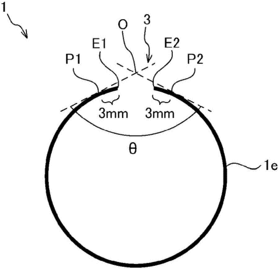
[0191] In the first embodiment, an example of the metal formed article of the present invention will be described. The metal formed article of the present invention includes a tubular portion having a slit. A section in a direction perpendicular to the axial direction of the tubular portion (section in the circumferential direction) is schematically shown in figure 1 middle. The metal formed product 1 includes a tubular portion 1 e in which the slit 3 is formed, and in a typical case, the metal formed product 1 consists of only the tubular portion 1 . In the slit 3, the two ends E1 and E2 face each other. In another viewpoint, the metal formed product 1 is a substantially closed section part (a tubular part having a substantially closed section). Here, the "substantially closed cross-section" means a cross-section in which a gap exists between two facing ends of a metal plate formed into a tubular shape. The substantially closed cross-section part may have a gap over the ...
no. 2 Embodiment approach
[0194] In the second embodiment, an example of the manufacturing method of the present invention and a mold used therefor will be described. In addition, in the following embodiment, an example of the case of manufacturing the metal formed article which consists only of a tubular part is demonstrated. The manufacturing method of the second embodiment includes step (i) and step (ii).
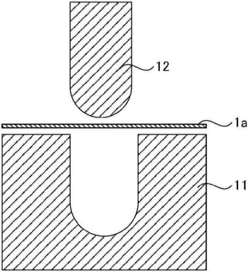
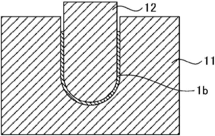
[0195] Process (i) is schematically shown in Figure 2A and 2B . First, if Figure 2A As shown, a metal plate (blank) 1 a is disposed between the die 11 and the punch 12 . The female die 11 and the punch 12 are dies for U forming. Next, if Figure 2B As shown, a metal plate 1a is press-formed to form a U-shaped portion 1b having a U-shaped cross section. Such as Figure 2C As shown, the U-shaped portion 1b has two ends E1 and E2.
[0196] In step (i), the size relationship between the width W of the portion of the metal plate that will become the tubular portion (tubular portion 1e) and ...
no. 3 Embodiment approach
[0209] In the third embodiment, another example of the manufacturing method of the present invention and the mold used therefor will be described. The manufacturing method of the third embodiment includes step (i) and step (ii). The step (i) is the same as the step (i) described in the second embodiment, and thus redundant description will be omitted.
[0210] exist Figure 4A The die used in the step (ii) of the third embodiment is schematically shown in . The mold 30 of the third embodiment is an example of the above-mentioned mold (b). The mold 30 includes an upper mold (first mold) 31 and a lower mold (second mold) 32 .
[0211] The upper mold 31 has a plate-shaped protrusion 33 for forming the slit 3 . The upper die 31 includes a main body portion 31a and a movable portion 31b that can relatively move with respect to the main body portion 31a. The movable part 31b is disposed on the top of the pressing surface 31ap of the main body part 31a, and includes a protrusion...
PUM
| Property | Measurement | Unit |
|---|---|---|
| tensile strength | aaaaa | aaaaa |
| tensile strength | aaaaa | aaaaa |
| length | aaaaa | aaaaa |
Abstract
Description
Claims
Application Information
 - R&D
- Intellectual Property
- Life Sciences
- Materials
- Tech Scout
- Unparalleled Data Quality
- Higher Quality Content
- 60% Fewer Hallucinations
Browse by: Latest US Patents, China's latest patents, Technical Efficacy Thesaurus, Application Domain, Technology Topic, Popular Technical Reports.
© 2025 PatSnap. All rights reserved.Legal|Privacy policy|Modern Slavery Act Transparency Statement|Sitemap|About US| Contact US: help@patsnap.com