Sparse array design method used for azimuth and pitching two-dimensional direction-finding
A sparse array and design method technology, applied in radio wave measurement systems, instruments, etc., can solve problems such as complex composition, high cost, and complex structure, and achieve the effects of low cost, low cost, and low system complexity
- Summary
- Abstract
- Description
- Claims
- Application Information
AI Technical Summary
Problems solved by technology
Method used
Image
Examples
Embodiment 1
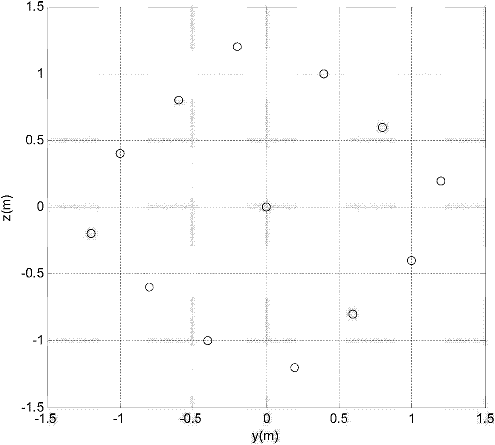
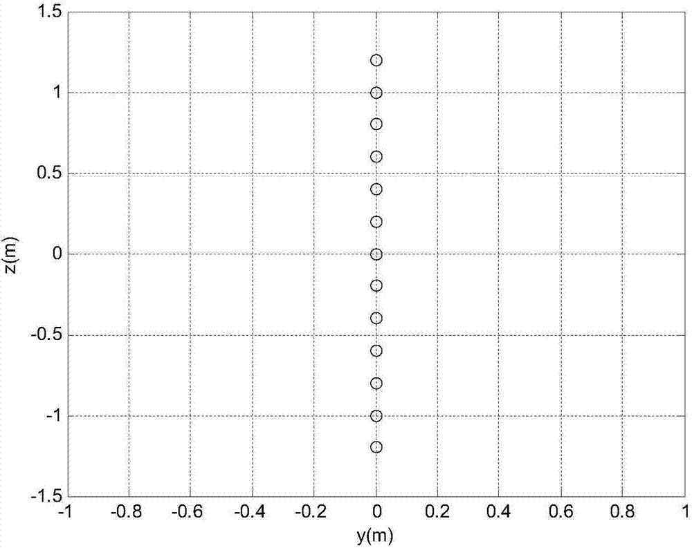
[0084] Taking the antenna design of an airport scene surveillance passive radar as an example, we design the working frequency of digital TV to be 600MHz, d=0.2m, and the theoretical formula (10) gives the signal with azimuth and elevation angles of (0° , 0°), (60°, 30°), (-60°, 30°), (60°, -30°), (-60°, -30°) incident beam patterns, see Figure 5 to Figure 9 As shown, the results in the figure are normalized by 20*log10(N). It can be seen from the figure that in the range of azimuth (-60°, 60°) and elevation (-30°, 30°), the side lobes of the beam pattern are all lower than 10dB; the target is incident at the center of the beam (0°, 0°) When , the formed beam pattern has better symmetry, and the main-side lobe ratio is 13dB; when the signal incident direction is other directions at that time, the side lobe of the elevation beam pattern will be raised. In the actual airport use, the installation elevation angle of the antenna is increased to 30° to effectively suppress multip...
PUM
 Abstract
Description
Claims
Application Information
 - R&D
- Intellectual Property
- Life Sciences
- Materials
- Tech Scout
- Unparalleled Data Quality
- Higher Quality Content
- 60% Fewer Hallucinations
Browse by: Latest US Patents, China's latest patents, Technical Efficacy Thesaurus, Application Domain, Technology Topic, Popular Technical Reports.
© 2025 PatSnap. All rights reserved.Legal|Privacy policy|Modern Slavery Act Transparency Statement|Sitemap|About US| Contact US: help@patsnap.com


