
Compensation subdividing method and device for high-resolution, high-precision and dual-photoelectric encoder

A photoelectric encoder and photoelectric encoding technology, which is applied in the direction of measuring devices, instruments, and conversion sensor outputs, can solve problems such as application limitations, and achieve the effects of low assembly and process costs, high resolution, and high integration

Active Publication Date: 2017-12-01
CHINA ELECTRONIS TECH INSTR CO LTD
View PDF7 Cites 7 Cited by
  • Summary
  • Abstract
  • Description
  • Claims
  • Application Information

AI Technical Summary

Problems solved by technology

Therefore, the clock pulse subdivision method is only suitable for occasions with good speed continuity, and its application is greatly limited.

Method used


Image

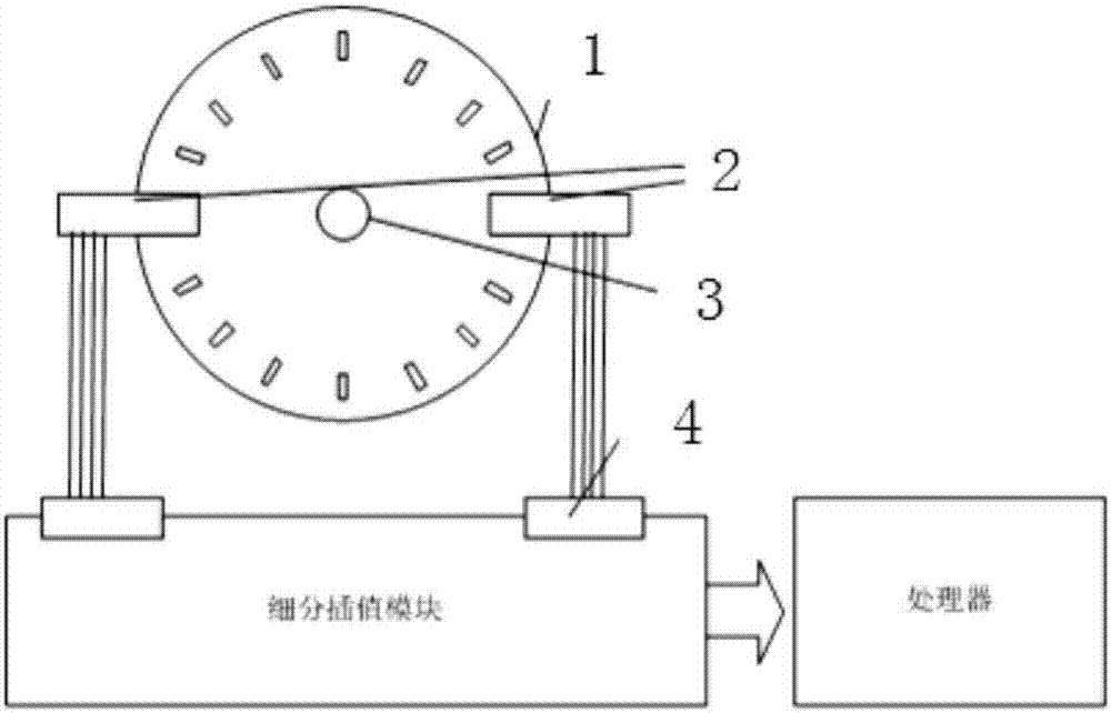
  • Compensation subdividing method and device for high-resolution, high-precision and dual-photoelectric encoder
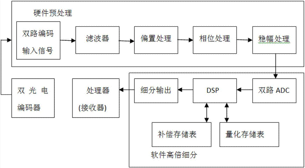
  • Compensation subdividing method and device for high-resolution, high-precision and dual-photoelectric encoder

Examples


Embodiment Construction

[0028] The present invention will be further described below in conjunction with the accompanying drawings and embodiments.

[0029] It should be pointed out that the following detailed description is exemplary and intended to provide further explanation to the present application. Unless defined otherwise, all technical and scientific terms used herein have the same meaning as commonly understood by one of ordinary skill in the art to which this application belongs.

[0030] It should be noted that the terminology used here is only for describing specific implementations, and is not intended to limit the exemplary implementations according to the present application. As used herein, unless the context clearly dictates otherwise, the singular is intended to include the plural, and it should also be understood that when the terms "comprising" and / or "comprising" are used in this specification, they mean There are features, steps, operations, means, components and / or combinatio...


PUM


Abstract

The invention discloses a compensation subdividing method and a device for a high-resolution, high-precision and dual-photoelectric encoder. The device comprises a photoelectric coding disk, a motor, a dual photoelectric reader and a subdividing difference module. The main rotation shaft of the photoelectric coding disk is coaxially connected with the rotating motor; the motor drives the photoelectric coding disk to rotate; the light emitted by the light emitting device of the photoelectric reader is chopped by the narrow slit of the photoelectric coding disk; a photosensitive device converts the signals formed by the penetrating light and blocking light into corresponding sine analog electrical signals; a subdividing interpolation module carries out high-power subdivision to the signals; and sampling is performed through the use of difference in phase relation of two-channel photoelectric coding signals; and at the same time, jitter compensation is performed for the coding signals.

Description

technical field [0001] The invention relates to a high-resolution and high-precision double photoelectric encoder compensation and subdivision device and method. Background technique [0002] Moiré fringes amplify the grating pitch. When the sensor moves a grating pitch, the photoelectric receiving circuit will generate a sine wave electrical signal, and obtain a resolution better than one grating pitch through interpolation, improving the resolution of the measurement system. This is the fundamental starting point for studying the Moiré fringe subdivision technology. Since the 1960s and 1970s, with the wide application of grid displacement sensors, Moiré fringe subdivision technology has become a research hotspot for grid displacement sensor manufacturers and experts in related fields at home and abroad. Various subdivision methods Emerge in endlessly, mainly including three categories of optical subdivision, mechanical subdivision and electronic subdivision. Among them, ...

Claims


Application Information

Patent Timeline
IPC IPC(8): G01D5/347
CPCG01D5/3473
Inventor 刘磊江升韩顺利项国庆吴威宋平李志增杨鹏张冰杭栋栋
Owner CHINA ELECTRONIS TECH INSTR CO LTD
Learn More