Automobile trim part surface treatment device

A technology for surface treatment devices and automotive trims, applied in the field of machinery, can solve problems such as inability to adjust intervals, winding, and reduced motor ergonomics, and achieves the advantages of preventing cleaning liquid or cleaning agent from splashing, improving cleaning efficiency, and reducing labor intensity. Effect

Inactive Publication Date: 2017-12-01
衢州市昊博专利技术推广有限公司
View PDF0 Cites 3 Cited by
  • Summary
  • Abstract
  • Description
  • Claims
  • Application Information

AI Technical Summary

Problems solved by technology

[0004] The above-mentioned device positions the decorative parts on the tooling, and utilizes the transfer of the conveyor belt to realize the passing of the decorative parts through the cleaning device on the lower surface of the upper mold, so as to realize the cleaning of the decorative parts. The interval cannot be adjusted. In the actual cleaning process, different types of decorations will be encountered. If the distance between the cleaning mechanism and the conveyor belt cannot be adjusted according to the specific conditions of the decorations, the cleaning mechanism will be greatly restricted. range of work, and the above-mentioned scheme also has a drawback. Several rotatable brushes are installed on the lower surface of the upper mold. If the number of brushes is too small, there will be areas that cannot be cleaned. If the number is too large, the brushes will There will be entanglement at the junction with the brush, causing damage to the motor. Frequent replacement of the motor will result in a decrease in work efficiency and an increase in cost

Method used


Image

  • Automobile trim part surface treatment device
  • Automobile trim part surface treatment device
  • Automobile trim part surface treatment device

Examples


Embodiment Construction

[0020] In order to make the technical means, creative features, goals and effects achieved by the present invention easy to understand, the present invention will be further described below in conjunction with specific embodiments.

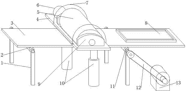
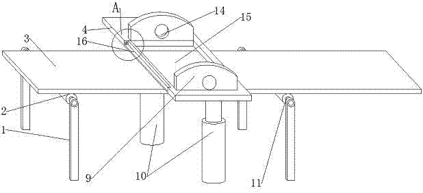
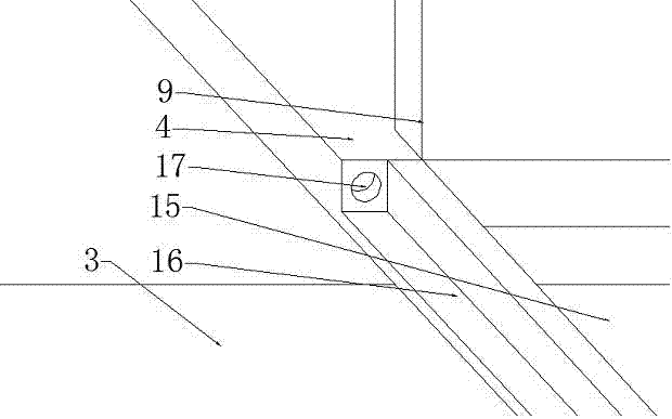
[0021] Such as Figure 1 to Figure 5 As shown, a surface treatment device for automotive trims includes a conveying device, a supporting device, a cleaning mechanism and interior decoration tooling 8, and the conveying device includes a support frame 1, a driving idler 11, a driven idler 2, and a driving motor 13 and the conveyor belt 3 between the driving idler 11 and the driven idler 2, the driving motor 13 is connected with the driving idler 11 through the belt 12, and the interior decoration tooling 8 is arranged on the conveyor belt 3, and the supporting device includes The adjustment mechanism and the support plate 4, the adjustment mechanism includes the lift cylinder 10 symmetrically arranged on both sides of the conveyor belt 3, the lift ...


PUM


Abstract

The invention discloses an automobile trim part surface treatment device and relates to the field of machinery. The automobile trim part surface treatment device comprises a conveying device, a support device, a cleaning mechanism and an interior trim part tool. The support device comprises an adjustment mechanism and a support plate. A vertically-through through groove is formed in the support plate. The two sides of the through groove are each provided with a vertical support seat. The side, located at one side of the support seats, of the support plate is provided with a rotating motor. The cleaning mechanism comprises a roller and a cleaning hair brush, wherein the cleaning hair brush is arranged on the outer wall of the roller in a sleeving manner. According to the automobile trim part surface treatment device, large interior trim parts inside an automobile are cleaned through the cleaning mechanism; labor intensity is lowered; cleaning efficiency is improved; the height of the cleaning mechanism is controlled through ascending-and-descending air cylinders; the distance between the cleaning hair brush and each interior trim part can be adjusted according to the height of the corresponding interior trim part after the interior trim part is placed horizontally; and application flexibility of the automobile trim part surface treatment device is improved.

Description

technical field [0001] The invention relates to the mechanical field, in particular to a surface treatment device for an automobile trim. Background technique [0002] During the production of automotive interior parts, dust and stains will adhere to the surface of the interior parts. If the interior parts with dust and stains are directly discarded, it will cause waste and high cost. However, it is inefficient and labor-intensive to manually clean the interior parts. [0003] The Chinese patent application number 2015211399176 discloses a cleaning device for automotive interior parts, which is characterized in that it includes an upper mold, a lower mold, a conveyor belt and an interior decoration tooling, and the upper mold can be lifted and lowered on the lower above the mold; the lower surface of the upper mold is provided with a cleaning device, the conveyor belt passes between the upper mold and the lower mold, and the interior decoration tooling is arranged on the co...

Claims


Application Information

Patent Timeline
Patent Type & Authority Applications(China)
IPC IPC(8): B08B1/02B08B1/20
CPCB08B1/20B08B1/12
Inventor 王金耀
Owner 衢州市昊博专利技术推广有限公司
Why Eureka
Try Eureka