
System and method for optical network

An optical path and optical coupling technology, which is applied in the direction of optical multiplexing system, multiplexing system selection device, transmission system, etc., can solve the problems of high cost, high delay, and high power consumption

Active Publication Date: 2017-11-28
HUAWEI TECH CO LTD
View PDF5 Cites 7 Cited by
  • Summary
  • Abstract
  • Description
  • Claims
  • Application Information

AI Technical Summary

Problems solved by technology

As data centers grow in size, internetwork can become complex, expensive and power-hungry
Data center networks can have limited throughput, high bandwidth convergence ratios, high latency, high power consumption, a large number of interconnects, and high costs

Method used


Image

  • System and method for optical network
  • System and method for optical network
  • System and method for optical network

Examples


Embodiment Construction

[0030] It should be understood at the outset that, although an illustrative implementation of one or more embodiments is provided below, the disclosed systems and / or methods may be implemented using any number of techniques, whether currently known or in existence. The invention should in no way be limited to the illustrative implementations, drawings and techniques illustrated below, including the designs and implementations illustrated and described herein, but rather be within the scope of the appended claims along with their full scope of equivalents Modified within.

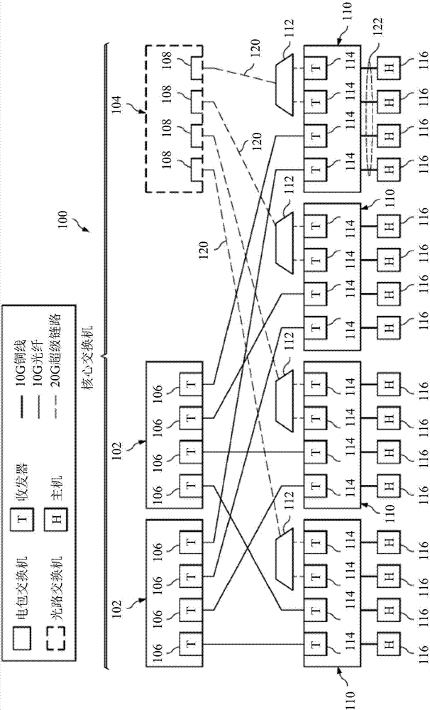
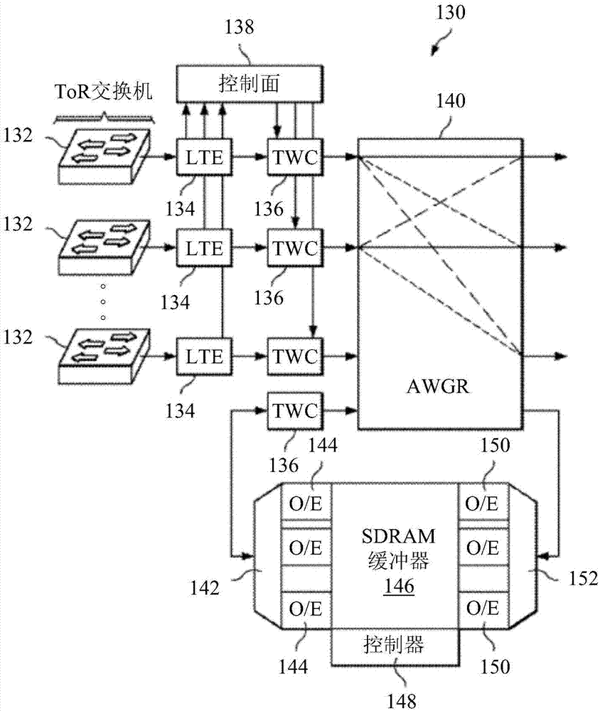
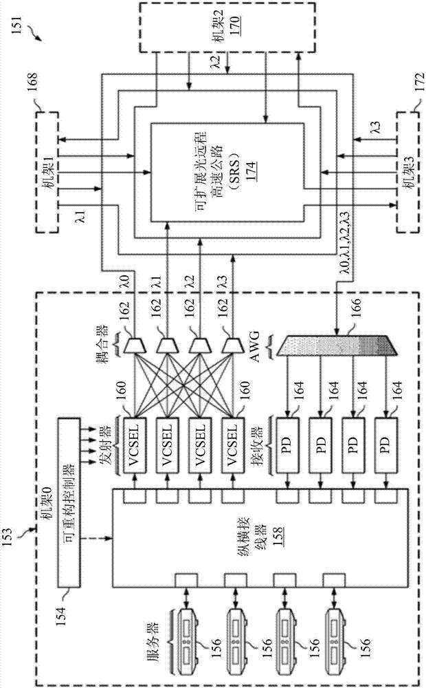
[0031] An embodiment optical network architecture has a centralized passive N x N optical switch matrix in a star configuration, where N is the number of input ports and the number of output ports of the optical switch matrix. In a star configuration, a single fiber connects the central optical circuit switching node ports and user nodes. The central optical switch is a wavelength switch. In wavelength swi...


PUM


Abstract

An optical circuit switching matrix includes a plurality of optical ports, each optical port being optically coupled to a respective one of a plurality of user nodes and an optical coupler having at least one input port optically coupled to the plurality of optical ports, and an output port. The optical circuit switching matrix also includes a wavelength demultiplexer having an input optically coupled to the output port of the optical coupler, and a plurality of output ports, each output port being optically coupled to a respective one of the plurality of optical ports.

Description

[0001] This application claims priority to earlier applications of U.S. Provisional Patent Application No. 62 / 128,627, filed March 5, 2015, and U.S. Conventional Patent Application No. 14 / 877,280, filed October 7, 2015, both of which The content of the earlier application is incorporated herein by reference. technical field [0002] The present invention relates to a system and method for optoelectronics, in particular to a system and method for optical networks. Background technique [0003] The increase in Internet traffic has driven the expansion of data center size. Data centers host data-intensive applications, and there is a lot of interaction between servers in the data center. As data centers grow in size, interconnect networks can become complex, expensive and power-hungry. Data center networks can have limited throughput, high bandwidth-to-convergence ratios, high latency, high power consumption, numerous interconnects, and high costs. Optical networks can incre...

Claims


Application Information

Patent Timeline
Patent Type & Authority Applications(China)
IPC IPC(8): G02B6/28
CPCH04J14/021H04J14/0275H04Q2011/0033H04Q2011/005H04Q2011/0032H04Q11/0005H04Q2011/0039H04Q2011/0058H04Q2011/0015H04Q2011/0016H04J14/0282H04B10/25H04B10/503H04B10/572H04Q2011/0018H04Q2011/0041
Inventor 蒋志平陈忱张筑虹李传东
Owner HUAWEI TECH CO LTD
Learn More