Long composite profile and its installation method

A composite profile and elongated technology, which is applied in the direction of load-bearing elongated structural members, building material processing, girders, etc., can solve the problem of low tear strength and achieve simple and cost-effective results

Active Publication Date: 2021-04-09
格勒德工业公司
View PDF4 Cites 0 Cited by
  • Summary
  • Abstract
  • Description
  • Claims
  • Application Information

AI Technical Summary

Problems solved by technology

Therefore, the tear strength near its ends is relatively low

Method used


Image

  • Long composite profile and its installation method
  • Long composite profile and its installation method
  • Long composite profile and its installation method

Examples


Embodiment Construction

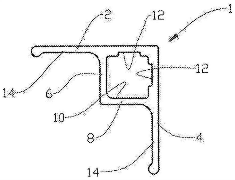
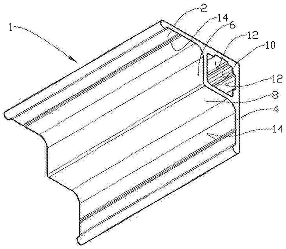
[0039] In the figures, reference numeral 1 designates a composite profile comprising a first flange 2 and a second flange 4 which together form an L-shaped profile. A first rib 6 protrudes inwardly from the first flange 2 and a second rib 8 protrudes inwardly from the second flange 4 . A part of the first flange 2 , a part of the second flange 4 , the first rib 6 and the second rib 8 form a closed channel 10 extending along the composite profile 1 .

[0040] The first rib 6 is narrower than the distal second flange 4 and the second rib 8 is narrower than the distal first flange 2 .

[0041] Inside the channel 10 , the first flange 2 and the second flange 4 are respectively formed with elongated nut bed grooves 12 . On the outside of the channel 10 , the first flange 2 and the second flange 4 are each formed with a corresponding longitudinally drilled slot 14 .

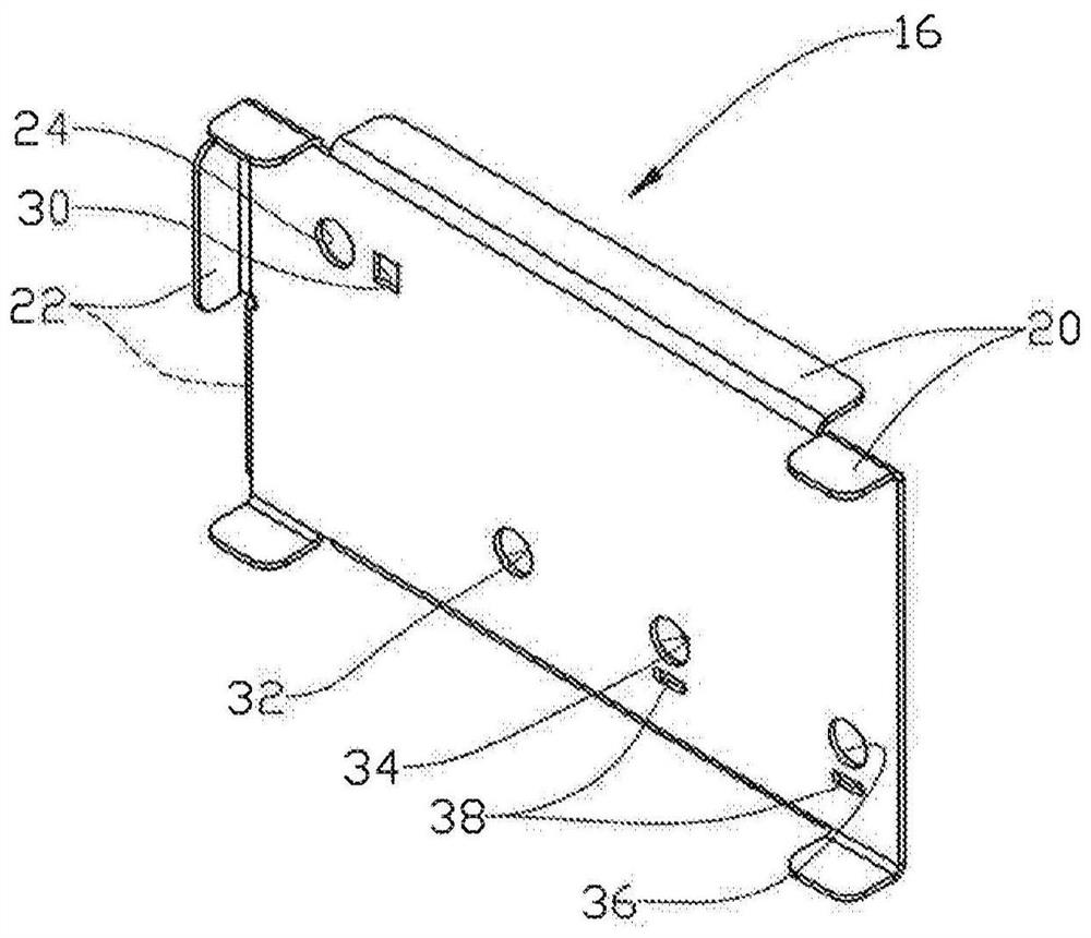
[0042] The drilling template 16 is designed to abut against the end 18 of the composite profile 1 outside the flan...


PUM


Abstract

A long composite profile (1), comprising a first flange (2) and a second flange (4), the first flange (2) and the second flange (4) together forming an L-shaped profile, each of the flanges (2, 4) in the L-shaped profile is provided with a first rib (6) and a second rib (8), and the first flange (2), the The second flange (4), the first rib (6) and the second rib (8) form a longitudinal closed channel (10) in the composite profile (1), and the installation of the composite profile method.

Description

technical field [0001] The invention relates to a long composite profile comprising a first flange and a second flange, the first flange and the second flange together form an L-shaped profile. The invention also includes a method of installing composite profiles Background technique [0002] Composite materials, for example in the form of or composites comprising glass, carbon or aramid fibers bonded by an adhesive (usually made of polyester, epoxy or polyurethane), are increasingly It is commonly used in load-carrying structures. [0003] Composite materials generally have a lower modulus of elasticity relative to metallic materials, and are therefore subject to greater deflection under the same loading conditions. [0004] Angular sections have several advantageous qualities which have led to their use in various load-bearing structures. The horn segments have a better bending stiffness in two planes and are easy to join together eg by bolts, since good use can be made...

Claims


Application Information

Patent Timeline
Patent Type & Authority Patents(China)
IPC IPC(8): E04C3/29E04B2/00
CPCE04C2003/0413E04C2003/0439E04C2003/046E04B1/5831F16B7/187H02G3/263E04B2001/2451E04C3/29E04B1/30E04G21/18
Inventor 阿恩·猗顿
Owner 格勒德工业公司
Why Eureka
Try Eureka