Electric servo system stiffness modeling method

A system stiffness and modeling method technology, applied in the field of electric servo system, can solve the problems of low servo stiffness, affecting system positioning accuracy, large loss of motion, etc., and achieve the effect of improving servo stiffness, reasonable mass distribution, and improving robustness

Inactive Publication Date: 2017-11-28
BEIJING AUTOMATION CONTROL EQUIP INST
View PDF4 Cites 2 Cited by
  • Summary
  • Abstract
  • Description
  • Claims
  • Application Information

AI Technical Summary

Problems solved by technology

In the actual use of the electric rudder system, when the performance indicators such as rudder deflection angle, maximum rudder deflection angular velocity, frequency band, linearity and overshoot meet the requirements, some new problems will still appear. The main reasons for the existence of these problems are One is that the servo stiffness characteristics of the rudder system cannot meet the requirements
If the servo stiffness is low, it is easy to cause flutter on the rudder surface
When flutter occurs, the aileron or rudder vibrates at a higher frequency with varying amplitude, which is extremely dangerous
[0003] If the servo system has low stiffness and large inertia, it will be difficult to obtain a high rotational speed, and at the same time, a large amount of loss of motion will be generated, which will increase the transmission error and affect the positioning accuracy of the system; Deformation, as well as the loss of motion caused by factors such as the dead zone of the control system and the operating error of the motor, cause the servo mechanism to lag or cause oscillation

Method used


Image

  • Electric servo system stiffness modeling method
  • Electric servo system stiffness modeling method
  • Electric servo system stiffness modeling method

Examples


Embodiment Construction

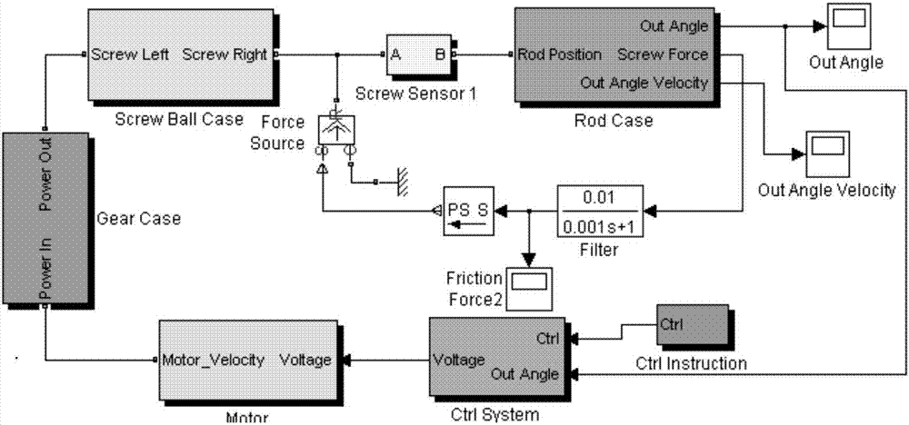
[0022] as attached figure 1 As shown, an electric servo system stiffness modeling method includes the following steps:

[0023] Step 1: Setting up the modeling foundation

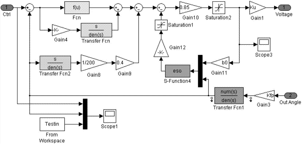
[0024] Matlab / Simulink establishes the control system of the electric rudder system;

[0025] Step 2: Establish model connection relationship

[0026] According to the situation of the object to be modeled, the model connection relationship is established, and the model prototype is implemented by calling the modules in Matlab / Simulink, especially Simscape;

[0027] When building a gear model, in addition to the conventional circuit, the upper and lower clearances, contact stiffness, contact damping, and initial angular position of the two rotating parts are also added. The upper and lower gaps, contact stiffness, contact damping, and initial angle position information of the above two rotating parts are set to initial values ​​as required.

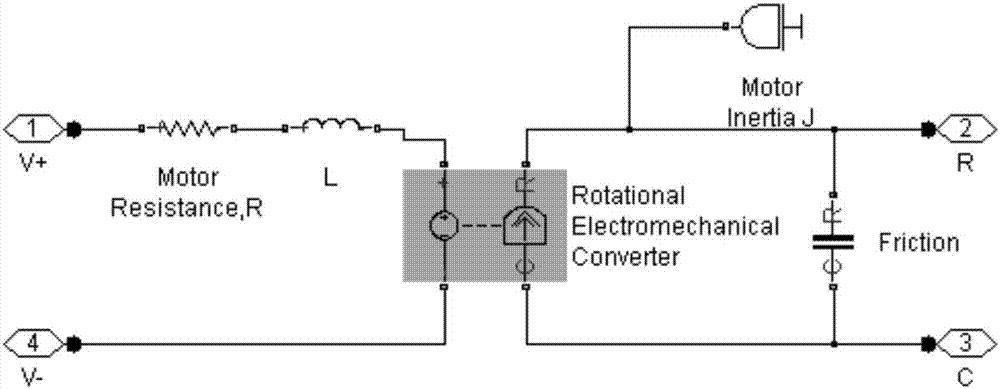
[0028] When building the model of the ball screw pair, in add...


PUM


Abstract

The invention belongs to the field of electric servo systems, and particularly relates to an electric steering system stiffness modeling method. The electric servo system stiffness modeling method comprises the following steps that firstly, a modeling base is set, wherein a control system of an electric steering system is established through Matlab / Simulink; secondly, a model connecting relation is built, wherein the model connecting relation is built according to the conditions of an object needing to be modeled, and modules called in the Matlab / Simulink are adopted by model prototypes. The electric servo system stiffness modeling method has the advantages that the method can be used for optimizing the parameters of the control system and improving the robustness of the system; the method can be used for guiding in optimization of the structural size of a transmission mechanism of an electric steering engine, so that the mass distribution of the electric steering engine is more reasonable; in the method, the principal factors influencing the electric servo system stiffness are demonstrated clearly, and the servo stiffness of the whole system is improved by optimizing the factors. The modeling method is high in precision and low in difficulty, and can be widely used in stiffness modeling of screw type electric steering engine systems.

Description

technical field [0001] The invention belongs to the field of electric servo systems, and in particular relates to a stiffness modeling method of an electric rudder system. Background technique [0002] The electric rudder system is composed of two parts, the steering gear amplifier and the electric steering gear. It is the main subsystem of the guidance control system, and its dynamic characteristics are directly related to the flight control quality of the missile. In the actual use of the electric rudder system, when the performance indicators such as rudder deflection angle, maximum rudder deflection angular velocity, frequency band, linearity and overshoot meet the requirements, some new problems will still appear. The main reasons for the existence of these problems are One is that the servo stiffness characteristics of the rudder system cannot meet the requirements. If the servo stiffness is low, it is easy to cause flutter on the rudder surface. When flutter occurs,...

Claims


Application Information

Patent Timeline
IPC IPC(8): G06F17/50
CPCG06F30/20
Inventor 刘源熊官送王永乐曹东海
Owner BEIJING AUTOMATION CONTROL EQUIP INST
Why Eureka
Try Eureka