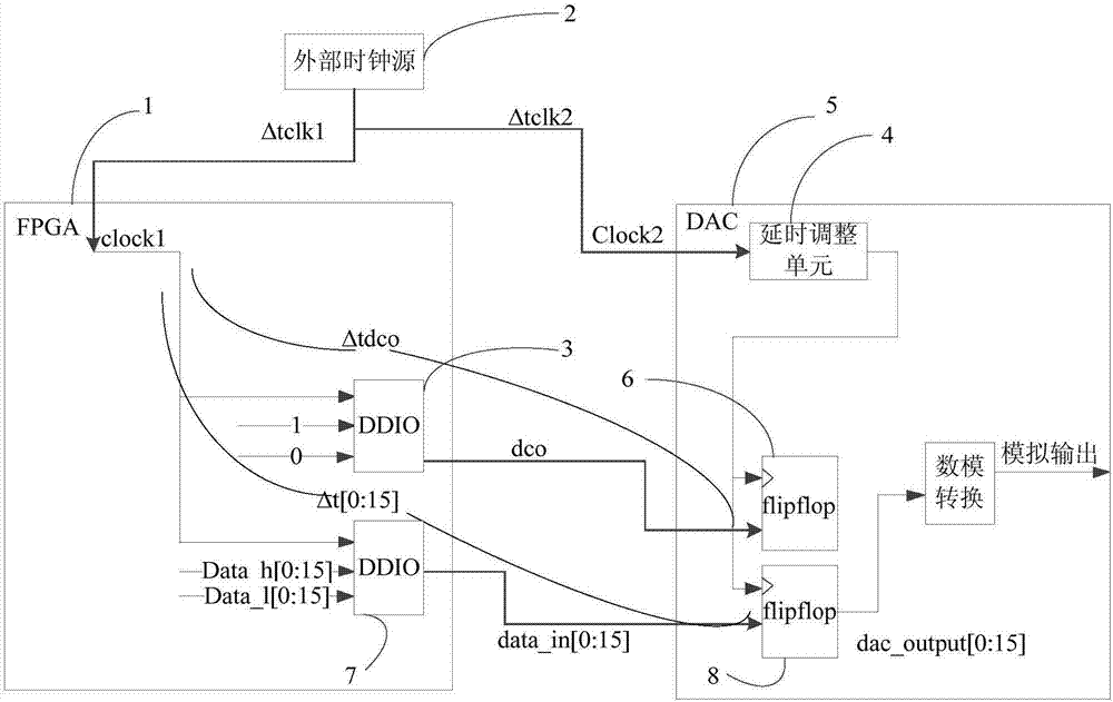
Data and clock alignment method and device, medium and magnetic resonance equipment
A clock alignment and clock technology, applied in the field of data processing, can solve problems such as fixed delay parameters, achieve the effect of dynamic alignment, improve data transmission efficiency, and improve alignment speed
- Summary
- Abstract
- Description
- Claims
- Application Information
AI Technical Summary
Problems solved by technology
Method used
Image
Examples
Embodiment 1
[0047] figure 1 It is a flowchart of a method for aligning data and clocks provided by Embodiment 1 of the present invention. The technical solution of this embodiment may be applicable to the case where data and clock are aligned. The method can be executed by the device for data alignment provided in the embodiment of the present invention, and the device can be implemented in software and / or hardware. Such as figure 1 As shown, the method specifically includes the following operations:
[0048] S110. Receive a data synchronization clock signal.
[0049] Exemplarily, the data synchronous clock signal is generated by the double-edge data input and output unit in the field programmable gate array module according to the third clock.
[0050] figure 2It is a schematic diagram of the radio frequency pulse transmission period and the idle period. The MR device generates a plurality of radio frequency pulse signals at a certain time interval, and there is an idle time inter...
Embodiment 2
[0071] Figure 7 It is a structural block diagram of an apparatus for aligning data and clocks provided in Embodiment 2 of the present invention. The device is configured to execute a method for aligning data and clocks provided in any of the foregoing embodiments. The device is applied during the idle time interval between the transmission of two radio frequency pulses, including:
[0072] A data synchronization clock signal receiving module 210, configured to receive a data synchronization clock signal;
[0073] The data synchronous clock signal acquisition module 220 is configured to acquire the data synchronous clock signal according to the first clock, delay the first clock by one time step after each acquisition, and continue to acquire all clock signals according to the delayed clock. The above-mentioned data synchronous clock signal, until collecting the data synchronous clock signal of a cycle;
[0074] A delay value adjustment module 230, configured to determine a...
Embodiment 3
[0093] Figure 8 A schematic structural diagram of a magnetic resonance device provided in Embodiment 3 of the present invention, such as Figure 8 As shown, the device includes a magnet, which is not shown in the figure, a processor 30, a memory 31, an input device 32 and an output device 33; the number of processors 30 in the device can be one or more, Figure 8 Take a processor 30 as an example; the processor 30, memory 31, input device 32 and output device 33 in the device can be connected by bus or other methods, Figure 8 Take connection via bus as an example.
[0094] Memory 31, as a computer-readable storage medium, can be used to store software programs, computer-executable programs and modules, such as the data synchronization clock signal receiving module 210 and the data synchronization clock signal acquisition module corresponding to the data alignment method in the embodiment of the present invention 220 . The delay value adjustment module 230 and the acquisiti...
PUM
 Abstract
Description
Claims
Application Information
 - R&D
- Intellectual Property
- Life Sciences
- Materials
- Tech Scout
- Unparalleled Data Quality
- Higher Quality Content
- 60% Fewer Hallucinations
Browse by: Latest US Patents, China's latest patents, Technical Efficacy Thesaurus, Application Domain, Technology Topic, Popular Technical Reports.
© 2025 PatSnap. All rights reserved.Legal|Privacy policy|Modern Slavery Act Transparency Statement|Sitemap|About US| Contact US: help@patsnap.com


