Filtering-free oil removing machine and method for removing oil through filtering-free oil removing machine

A deoiler and oil drum technology, which is used in the lubrication of engines, centrifuges, mechanical equipment, etc., can solve the problems of difficult cleaning of the deoiler, affecting the efficiency and quality of deoiling, time-consuming and laborious, and achieving a simple and easy structure. Clean, cleverly conceived effects

Active Publication Date: 2017-11-28
宁波市北仑区丛峰机械有限公司
View PDF7 Cites 4 Cited by
  • Summary
  • Abstract
  • Description
  • Claims
  • Application Information

AI Technical Summary

Problems solved by technology

[0003] The present invention mainly provides a filter-free deoiler with high deoiling efficiency and good quality, which can automatically separate the grease adhering to the steel shavings, and the separated grease does not need secondary separation and filtration. The method of deoiling with a filter-free deoiler solves the problem in the prior art that the separated cooling lubricating oil needs to be separated and filtered again, which is time-consuming and laborious. At the same time, metal shavings will block the small holes of the deoiling cylinder wall during the process. , resulting in extremely difficult cleaning of the deoiling cylinder, affecting technical problems such as deoiling efficiency and quality

Method used


Image

  • Filtering-free oil removing machine and method for removing oil through filtering-free oil removing machine
  • Filtering-free oil removing machine and method for removing oil through filtering-free oil removing machine

Examples


Embodiment

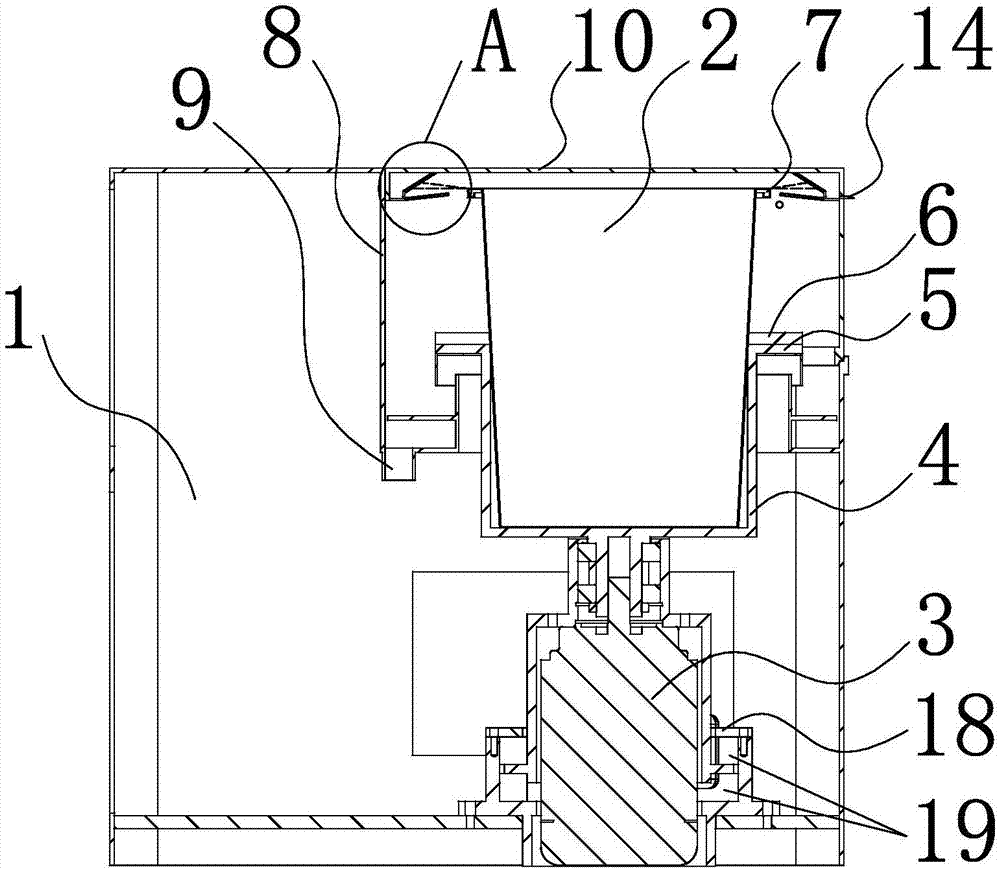
[0027] Such as figure 1 As shown, a filter-free deoiler of the present invention includes a box body 1, and the box body 1 has a motor positioning cover 18 on the bottom surface of the box body 1, and the output shaft 31 of the drive motor 3 is upwardly matched and embedded. It is installed in the motor positioning cover 18, and the corresponding drive motor 3 in the motor positioning cover 18 is covered with two anti-vibration and anti-swing rings 19 made of rubber, and the anti-vibration and anti-swing ring 19 on the top is clamped on the outside of the drive motor 3. Between the upper surface of the horizontal partition and the top surface of the corresponding motor positioning cover 18, the shockproof and anti-swing ring 19 below is clamped between the lower surface of the horizontal partition outside the drive motor 3 and the bottom surface of the corresponding motor positioning cover 18, and the output shaft 31 extends to the outside of the motor positioning cover 18, a ...


PUM


Abstract

The invention relates to an oil removing machine and provides a filtering-free oil removing machine and a method for removing oil through the filtering-free oil removing machine. The filtering-free oil removing machine is simple in structure and can automatically separate out oil adhering to steel cuttings and is high in oil removing efficiency and good in quality, and separated oil is free of secondary separation and filtering. The technical problems that in the prior art, separated cooling lubrication oil needs secondary separation and filtering, time and labor are wasted, and as small holes of the wall of an oil removing barrel are blocked by metal cuttings in the process, the oil removing barrel is extremely difficult to clean, and the oil removing efficiency and quality are affected are solved. The filtering-free oil removing machine comprises a tank and an oil throwing barrel suspended in the tank, a drive motor is arranged at the position, corresponding to the oil throwing barrel, of the bottom face of the tank, an output shaft of the drive motor faces upwards and drives the oil throwing barrel to rotate, an opening of the oil throwing barrel faces upwards, and a containing cavity of the oil throwing barrel is in a circular truncated cone shape with a large opening and a small bottom.

Description

technical field [0001] The invention relates to a deoiler, in particular to a filter-free deoiler with simple structure, which can automatically separate the grease adhering to steel shavings, and the separated grease does not need secondary separation and filtration and adopts a filter-free deoiler. The method of deoiling the oil machine. Background technique [0002] In the process of mechanical processing, it is often necessary to use cooling lubricating oil to cool the workpiece, so that a large amount of cooling lubricating oil will adhere to the metal shavings generated during the machining process. The recycling of lubricating oil not only increases production costs, pollutes the environment, but also affects the recycling of metal chips. Therefore, deoilers are generally used to separate metal chips and attached grease. Existing deoilers generally use mechanical centrifugal separation. The principle is that through the high-speed rotation of the porous inner cylinde...

Claims


Application Information

Patent Timeline
Patent Type & Authority Applications(China)
IPC IPC(8): F16N39/06B04B1/00
CPCB04B1/00F16N39/06
Inventor 甘祥飞
Owner 宁波市北仑区丛峰机械有限公司
Why Eureka
Try Eureka