Manual clamping device

A manual clamping device and clamping rod technology, applied in the direction of manipulators, manufacturing tools, etc., can solve the problems of unreasonable shape design of clamping parts, inconvenient loosening of workpiece clamping, and easy interference in the movement of clamping parts.

Pending Publication Date: 2017-11-28
ANHUI HANGXIN MACHINERY MFG
View PDF0 Cites 0 Cited by
  • Summary
  • Abstract
  • Description
  • Claims
  • Application Information

AI Technical Summary

Problems solved by technology

[0002] During the processing of mechanical products, mechanical parts usually generate a lot of heat due to the interaction between the tool and the workpiece, causing the surface temperature of these parts to be too high to be grasped directly by hand. Traditionally used to grasp these parts The device is either complicated in structure or cumbersome to operate. It is easy to interfere when the clamping part moves, it is inconvenient to clamp or loosen the workpiece, the shape design of the clamping part is unreasonable, and the outer surface of the workpiece cannot be tightly fitted when clamping the workpiece. It causes unstable clamping, so design a simple structure, convenient operation, free rotation of the chuck, easy clamping or loosening of the workpiece, the left end of the chuck and the clamping rod is designed as an arc-shaped inner surface, and the workpiece is in contact with the workpiece when clamping. It is necessary to have a tight fit and a stable clamping device

Method used


Image

  • Manual clamping device

Examples


Embodiment Construction

[0013] In order to make the technical means, creative features, goals and effects achieved by the present invention easy to understand, the present invention will be further described below in conjunction with specific illustrations.

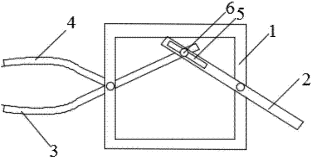
[0014] A manual clamping device, including a bracket 1, a handle 2, a chuck 3, a clamping rod 4, a chute 5, and a sliding rod 6. The bracket 1 is a frame-shaped structure, and the middle position of the handle 2 is on the right side of the bracket 1. The frame constitutes a revolving pair, the left end of the handle 2 is provided with a chute 5, the right end of the chuck 3 is provided with a slide bar 6, and the slide bar 6 is embedded in the chute 5, the middle position of the chuck 3 is in the middle of the left end of the bracket 1 Composed of a rotating pair, pull the handle 2, the chuck 3 can rotate around the bracket 1, and the left end of the chuck 3 can be conveniently connected with the clamping rod 4 to realize the clamping and looseni...


PUM


Abstract

The invention discloses a manual clamping device, and belongs to the technical field of mechanical device design. The manual clamping device comprises a support, a handle, a clamping head, a clamping rod, a sliding slot and a sliding rod, wherein the support adopts a framework-shaped structure; the middle part of the handle and a right framework of the support form a revolute pair; the sliding slot is formed in the left end part of the handle; the sliding rod is arranged on the right end part of the clamping head; the sliding rod is embedded into the sliding slot; the middle part of the clamping head and the middle part of the left end of the support form a revolute pair; the handle is moved, the clamping head can rotate around the support, and the left end of the clamping head and the clamping rod can conveniently clamp and loosen a workpiece. The manual clamping device disclosed by the invention is simple in structure and convenient to operate, is closely fit with the workpiece and firmly clamps the workpiece when the workpiece is clamped, and conveniently clamps or loosens the workpiece; the sliding rod is unlikely to drop out of the sliding slot.

Description

technical field [0001] The invention relates to the technical field of mechanical device design, in particular to a manual clamping device. Background technique [0002] During the processing of mechanical products, mechanical parts usually generate a lot of heat due to the interaction between the tool and the workpiece, causing the surface temperature of these parts to be too high to be grasped directly by hand. Traditionally used to grasp these parts The device is either complicated in structure or cumbersome to operate. It is easy to interfere when the clamping part moves, it is inconvenient to clamp or loosen the workpiece, the shape design of the clamping part is unreasonable, and the outer surface of the workpiece cannot be tightly fitted when clamping the workpiece. It causes unstable clamping, so design a simple structure, convenient operation, free rotation of the chuck, easy clamping or loosening of the workpiece, the left end of the chuck and the clamping rod is d...

Claims


Application Information

Patent Timeline
IPC IPC(8): B25J1/02
CPCB25J1/02
Inventor 赵锁方桂云
Owner ANHUI HANGXIN MACHINERY MFG
Why Eureka
Try Eureka