Antenna adaptation method, antenna and terminal
An antenna and terminal technology, applied to antennas, devices that enable antennas to work in different bands at the same time, antenna components, etc., to achieve the effects of low heat generation, low power consumption, and improved communication signal quality
- Summary
- Abstract
- Description
- Claims
- Application Information
AI Technical Summary
Problems solved by technology
Method used
Image


Examples
Embodiment 1
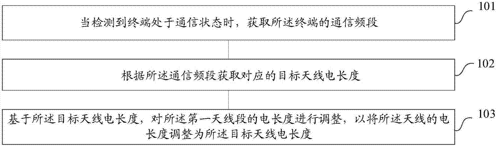
[0056] refer to figure 1 , shows a flow chart of the steps of an antenna adaptation method according to Embodiment 1 of the present invention. The antenna includes at least a first antenna section, and the first antenna section is made of a deformable alloy. The method of antenna adaptation may include the following steps:
[0057] Step 101: When it is detected that the terminal is in the communication state, acquire the communication frequency band of the terminal;
[0058] Step 102: Obtain the corresponding target antenna electrical length according to the communication frequency band;
[0059] Step 103: Adjust the electrical length of the first antenna segment based on the target antenna electrical length, so as to adjust the electrical length of the antenna to the target antenna electrical length.
[0060] The antenna adaptation method provided by the embodiment of the present invention can obtain the current communication frequency band of the terminal when it is detect...
Embodiment 2
[0062] refer to figure 2 , shows a flow chart of the steps of a method for adapting an antenna according to Embodiment 2 of the present invention, the antenna at least includes a first antenna section, the first antenna section is made of a deformable alloy, and the first The antenna segment is connected to the control circuit, and the control circuit has circuit parameters. The antenna adaptation method in the embodiment of the present invention may include the following steps:
[0063] Step 201: Establish an adaptation relationship table between the communication frequency band and the electrical length of the target antenna;
[0064] Specifically, the communication frequency band is used to carry wireless spectrum resources operated by communication operators. Different operators have different communication frequency bands. For example, the communication frequency band owned by China Mobile, for TD-LTE (TimeDivision Long Term Evolution, time-sharing long-term evolution) ...
Embodiment 3
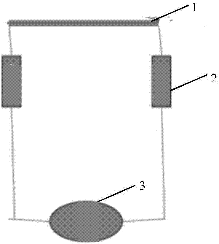
[0139] The embodiment of the present invention also discloses an antenna. The antenna includes at least a first antenna section, the first antenna section is made of deformable alloy, and the electrical length of the first antenna section is suitable for the communication frequency band of the terminal. match.
[0140]In a preferred embodiment of the present invention, the antenna further includes a second antenna segment, and the physical length of the second antenna segment is a fixed value.
[0141] In a preferred embodiment of the present invention, the first antenna section is connected to a control circuit, and the control circuit adjusts the physical length of the first antenna section according to circuit parameters.
[0142] In a preferred embodiment of the present invention, said circuit parameters include voltage and / or current.
[0143] In a preferred embodiment of the present invention, an inductor is connected in series at both ends of the first antenna segment....
PUM
 Abstract
Description
Claims
Application Information
 - Generate Ideas
- Intellectual Property
- Life Sciences
- Materials
- Tech Scout
- Unparalleled Data Quality
- Higher Quality Content
- 60% Fewer Hallucinations
Browse by: Latest US Patents, China's latest patents, Technical Efficacy Thesaurus, Application Domain, Technology Topic, Popular Technical Reports.
© 2025 PatSnap. All rights reserved.Legal|Privacy policy|Modern Slavery Act Transparency Statement|Sitemap|About US| Contact US: help@patsnap.com