Rapid fault detection method and detection system
A detection method and detection system technology, applied in the direction of measuring electricity, measuring devices, measuring electrical variables, etc., to achieve the effects of simplifying debugging difficulty, reducing time, and reducing working hours
- Summary
- Abstract
- Description
- Claims
- Application Information
AI Technical Summary
Problems solved by technology
Method used
Image
Examples
Embodiment 1
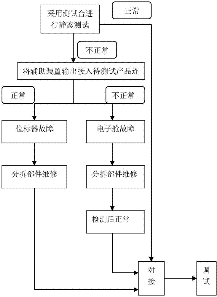
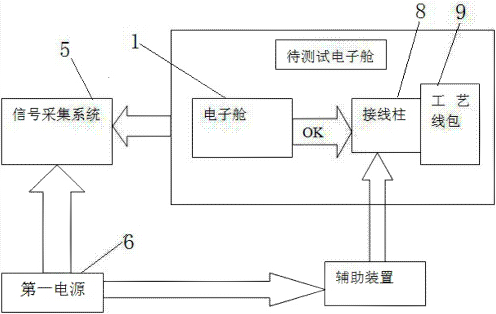
[0023] Such as figure 1 As shown, the fault rapid detection method provided by the embodiment of the present invention is used to quickly detect the fault of the product to be tested. 2 is provided with an X1 connection terminal board 4 for welding the connecting wire harness 3; including the following steps, placing the auxiliary device for generating the reference signal on the test bench; fixing the signal ground wire of the auxiliary device on the product to be tested; The auxiliary device is provided with a signal output probe, the signal output probe is contacted with the X1 terminal block 4, and the signal acquisition system 5 is used to collect the static image of the product to be tested; if the static image is normal, it indicates that the fault location is in the position marker 2; If the fault persists, it is in electronic compartment 1.
[0024] Wherein, the signal acquisition system 5 is an existing signal acquisition system 5 and will not be described in detail...
Embodiment 2
[0028] On the basis of Example 1, such as figure 2 As shown, the X1 wiring terminal board 4 is provided with inner A, B, C, D area signal terminals and outer A, B, C, D area signal terminals for inputting signals to the electronic cabin 1; A, B, C, D area signal terminals and outer A, B, C, D area signal terminals connection harness 3; connect the signal output probe of the auxiliary device to the inner A, B, C, D area signal terminals and the outer A, B, C, D area signal terminals in sequence. Signal terminals in areas B, C, and D, and use the signal acquisition system 5 to collect the static image of the product to be tested; if the static image is normal, it means that the fault location is in the position marker 2; if the fault persists, it is in the electronic cabin 1.
[0029] By setting the signal terminals in the inner A, B, C, and D areas and the outer A, B, C, and D area signal terminals on the X1 terminal board 4, it is convenient to connect the wire harness 3 for ...
Embodiment 3
[0033] On the basis of Example 1, such as figure 2 As shown, when the product to be tested uses a light source to perform a static drawing test, the product to be tested has no output failure in the outer D area, and the output reference signal output by the auxiliary device is input at the signal terminal of the outer D area through the auxiliary device. (also claiming analog signal), use signal acquisition system 5 to gather outer D area output signal simultaneously, find that outer D area output signal is normal, can determine that the fault position that outer D area does not have output is in position mark device 2 this moment.
PUM
 Abstract
Description
Claims
Application Information
 - R&D
- Intellectual Property
- Life Sciences
- Materials
- Tech Scout
- Unparalleled Data Quality
- Higher Quality Content
- 60% Fewer Hallucinations
Browse by: Latest US Patents, China's latest patents, Technical Efficacy Thesaurus, Application Domain, Technology Topic, Popular Technical Reports.
© 2025 PatSnap. All rights reserved.Legal|Privacy policy|Modern Slavery Act Transparency Statement|Sitemap|About US| Contact US: help@patsnap.com


