


Quick Research
Generate reliable direction feasibility study reports for your R&D in just a few steps.

Technical Q&A
Discover and master advanced knowledge NOW. Basics, ideas, possibilities, all at once.

Find Solutions
As an expert in R&D theories, this can generate solutions to your technical problems instantly.

Evaluate Feasibility
Analyze your overall solution with one click, know your potential R&D risks in advance.

Monitor Landscape
Get weekly tech updates, stay abreast of the latest tech innovations and key insights.
Air pressure testing method and system
A gas pressure test and gas pressure technology, applied in the field of detection, can solve problems such as difficulty in quantification, and achieve the effects of high sensitivity, convenient volume conversion, and easy leakage
- Summary
- Abstract
- Description
- Claims
- Application Information
AI Technical Summary
Problems solved by technology
Method used
Image

Examples
Embodiment approach 1
[0038] combined with figure 1 An embodiment of the air pressure test system of the present invention for performing air pressure tests on packers is described.
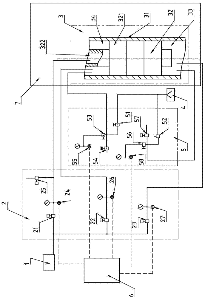
[0039] Such as figure 1 As shown, this embodiment adopts a modular design concept to divide the packer air pressure test system into different functional modules, including a test gas source 1, a high pressure test module 2, a packer setting test module 3, a vacuum device 4, Low-voltage test module 5, data processing module 6, temperature rise and heat preservation module 7.
[0040] Among them, in the packer setting test module 3, the tested packer 32 is set in the test wellbore 33, and the packer 32 and its seal 321 divide the inner chamber of the test wellbore 31 into a lower chamber 33 and an upper chamber. 34, wherein the part of the cavity containing the packer central tube 322 is the upper cavity 34, and the part of the cavity that does not accommodate the packer central tube 322 is the lower cavity 33.
[0...
Embodiment approach 2
[0049] An embodiment of the method for performing a pneumatic test on a packer of the present invention will be described in conjunction with Embodiment 1. This embodiment is to test the central tube.
[0050] First, install the tested packer in the test wellbore 31 and set it.
[0051] Then open the upper cavity low pressure test switch valve 51, the lower cavity low pressure test switch valve 52, start the vacuum device 4, extract the air in the upper cavity 34, the lower cavity 33 to a vacuum state, and the data processing module 6 passes the upper cavity low pressure pressure sensor 56, The lower chamber low-pressure pressure sensor 58 records the initial pressures of the upper chamber 34 and the lower chamber 33 .
[0052] Open the center pipe high pressure test switch valve 21, close the upper cavity high pressure test switch valve 22 and the lower cavity high pressure test switch valve 23, start the test gas source 1, and raise the gas pressure in the packer center tub...
Embodiment approach 3
[0057] Another embodiment of the method for performing a pneumatic test on a packer according to the present invention will be described in conjunction with Embodiment 1. In this embodiment, the upper chamber is tested at a high temperature.
[0058] First, install the tested packer in the test wellbore 31 and set it.
[0059] Open the upper chamber high-pressure test switch valve 22, close the central tube high-pressure test switch valve 21, the lower chamber high-pressure test switch valve 23, start the test gas source 1, and increase the gas pressure in the upper chamber 34 to the standard API SPEC 11D1 "Petroleum and Natural Gas Industry- Downhole Tools - Packers and Bridge Plugs" test pressure, pressure stabilization, upper chamber high pressure pressure sensor 26 transmits the pressure signal at this time to the data processing module 6 .
[0060] Open the lower chamber low pressure test switch valve 52, start the vacuum device 4, extract the air in the lower chamber 33...
PUM
 Abstract
Description
Claims
Application Information
 - R&D Engineer
- R&D Manager
- IP Professional
- Industry Leading Data Capabilities
- Powerful AI technology
- Patent DNA Extraction
Browse by: Latest US Patents, China's latest patents, Technical Efficacy Thesaurus, Application Domain, Technology Topic, Popular Technical Reports.
© 2024 PatSnap. All rights reserved.Legal|Privacy policy|Modern Slavery Act Transparency Statement|Sitemap|About US| Contact US: help@patsnap.com