
Gear measurement center non-contact measuring device

A non-contact, measuring device technology, applied in the direction of measuring devices, optical devices, instruments, etc., to achieve the effect of convenient use and measurement, avoiding image processing process, and accurate results

Pending Publication Date: 2017-11-24
思格迈斯特智能装备有限公司
View PDF0 Cites 2 Cited by
  • Summary
  • Abstract
  • Description
  • Claims
  • Application Information

AI Technical Summary

Problems solved by technology

Although many measuring instrument companies have produced some new image measuring instruments for non-contact measurement, they all use CCD for non-contact measurement of gear profile image acquisition, and image processing is also used in the later stage of measurement The software performs complex image processing, such as using MATLAB to blur the image, etc.

Method used


Image

  • Gear measurement center non-contact measuring device
  • Gear measurement center non-contact measuring device
  • Gear measurement center non-contact measuring device

Examples


Embodiment Construction

[0015] In order to make the technical means, creative features, goals and effects achieved by the present invention easy to understand, the present invention will be further described below in conjunction with specific embodiments.

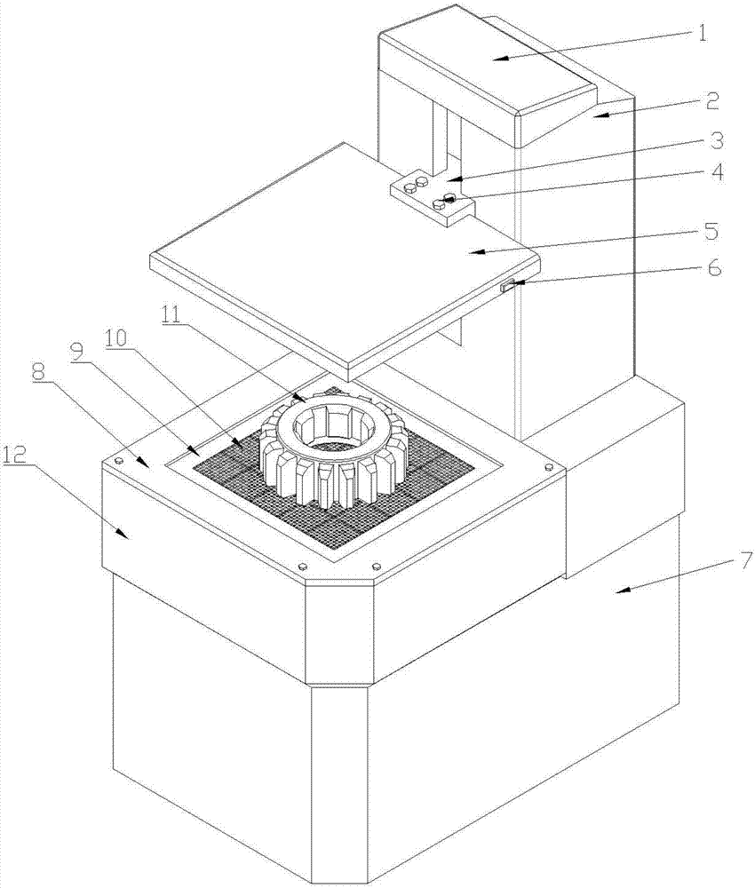
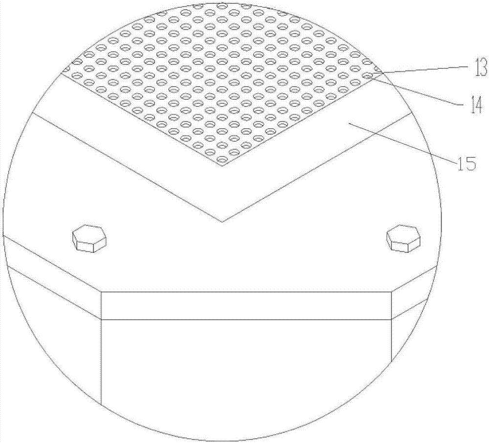
[0016] Such as Figure 1-3 As shown, a non-contact measuring device for a gear measuring center includes an optical signal transmitting device 5, an optical signal receiving board 11, a lifting device 2 and a base 7, and the measuring platform 12 is installed on the front side of the lifting device 2, A protective frame 8 is installed on the measuring platform 12, and the protective frame 8 is fixed to the measuring platform 12 by bolts 4. There is a square through hole in the middle of the protective frame, and the square through hole position in the middle of the protective frame 8 is An optical signal receiving board 10 is installed on it, a transparent glass plate 9 is arranged on the protective frame 8 above the optical signal receiving board...


PUM


Abstract

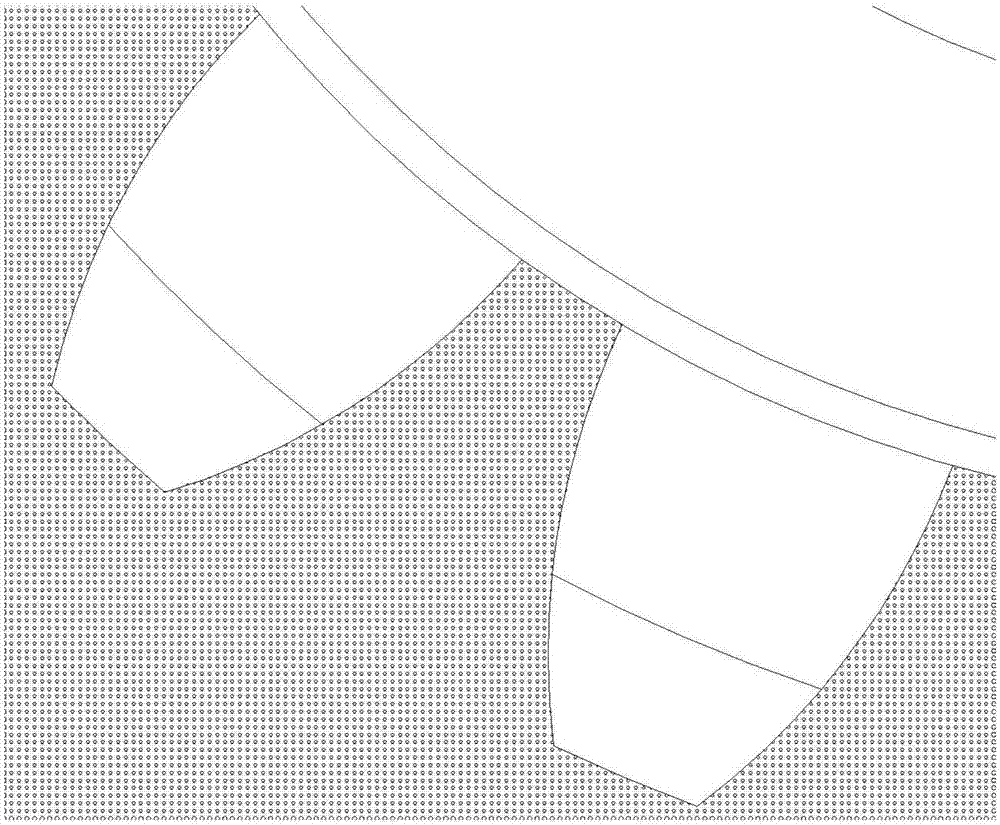
The invention relates to the technical field of a gear measurement center. A non-contact measuring device comprises an optical signal emitter, a measurement platform, a lift device and a base. The lift device is arranged on the base; the lift device is provided with an H-shaped lifting slide block; the optical signal emitter is connected with the lifting slide block through a bolt; the measurement platform is arranged at the front side of the lift device; the measurement platform is provided with a protection frame; the protection frame is fixedly arranged on the measurement platform through bolts; the protection frame is equipped with a fiber measuring plate at the place of a square through hole in the middle of the protection frame; and the protection frame above the fiber measuring plate is provided with a transparent glass plate. The non-contact measuring device can realize geometric parameter measurement of gear contour innovatively by utilizing optical fibers; through non-contact measurement, the measurement result is allowed to be more accurate, and the gear tooling process before conventional contact measurement is saved; and contour point data is obtained directly, and such mode is more convenient than an image processing mode.

Description

technical field [0001] The invention relates to the technical field of gear measurement centers, in particular to a non-contact measurement device for a gear measurement center. Background technique [0002] The equipment of the gear measurement center is the equipment that can measure various shapes of spur gears and helical gears. Measuring gear hobs, worm gear hobs, shaving knives, radial shaving knives, gear shaper knives and other gear tools. It can also measure workpieces such as worm gears, worm straight bevel gears, helical bevel gears, and cams. It can be widely used in scientific research departments and factory measurement rooms such as automobiles, machine tools, instruments, aviation, aerospace, and national defense industries. [0003] The measurement of gears in existing gear measurement centers is mostly contact measurement. For example, the gear measurement centers produced by WENZEL Company in Germany, M&M Company in the United States, Haliang Company in...

Claims


Application Information

Patent Timeline
IPC IPC(8): G01B11/24
CPCG01B11/2416
Inventor 刘抗李四朋李毅力杨其龙刘洪坤王建洋陆新福
Owner 思格迈斯特智能装备有限公司
Learn More