Online temperature detection device

A detection device and temperature detector technology, applied in the direction of measuring devices, thermometers, thermometers, etc., can solve the problems of the influence of finished product performance, great influence of finished product performance, large temperature error of sintered body, etc., and achieve convenient installation and disassembly, temperature Detecting Accurate and Reliable Effects

Active Publication Date: 2017-11-24
郑州登电科诚新材料有限公司
View PDF8 Cites 3 Cited by
  • Summary
  • Abstract
  • Description
  • Claims
  • Application Information

AI Technical Summary

Problems solved by technology

[0002] In the process of firing ceramic billets in a kiln, the control of the sintering temperature directly affects the quality of the finished product. At present, a temperature detector is installed in the kiln to detect the temperature of the inner cavity of the kiln online in real time, and according to the detected temperature of the kiln The furnace cavity temperature controls the sintering heating temperature and heating time. This online detection system has the following problems: the detection temperature is the temperature of the kiln cavity, not the actual temperature of the sintered body. The error, especially the temperature error of the sintered body at the middle position of the kiln car is larger, and the actual temperature change of the sintered body itself has a great influence on the performance of the later finished product. The existing online detection system cannot accurately measure the temperature of the sintered body during the firing process The actual temperature and temperature changes, especially the warm-up phase and cooling phase
If the temperature and time cannot be precisely controlled during the kiln firing process, it will affect the performance of the finished product, and even the finished product cannot reach the best performance index it should have achieved.

Method used


Image

  • Online temperature detection device
  • Online temperature detection device

Examples


Embodiment Construction

[0016] The present invention will be further described below in conjunction with the accompanying drawings and preferred embodiments, but the protection scope of the present invention is not limited thereby.

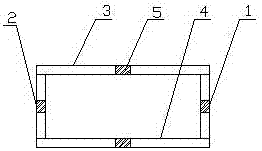
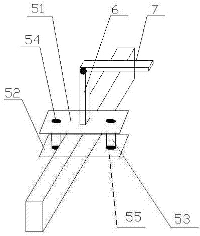
[0017] A temperature online detection device, such as Figure 1-2 As shown, including the kiln car entering and leaving the kiln, the outer frame of the front outer frame 1, rear outer frame 2, left outer frame 3, and right outer frame 4 of the kiln car is provided with a fixing seat 5, and the fixing seat includes an upper The fixed plate 51 and the lower fixed plate 52, the upper fixed plate 51 is provided with two first through holes 54 near the two ends, and the lower fixed plate is provided with a second through hole 55 adapted to the first through hole 54 , the upper fixing plate 51 and the lower fixing plate 52 are respectively located on the upper and lower sides of the same outer frame, the two first through holes 54 are respectively located on the left and righ...


PUM


Abstract

The invention belongs to the technical field of heating temperature measurement and control in sintering body firing technologies, and particularly relates to an online temperature detection device. The online temperature detection device comprises a kiln car entering and exiting a kiln, and at least one fixing base is arranged among outer frames of the kiln car; a telescopic vertical rod is arranged on each fixing base, one end of each telescopic vertical rod is fixed to the corresponding fixing base, the other end of each telescopic vertical rod is connected with one end of a corresponding telescopic transverse rod, the other end of each telescopic transverse rod is provided with a temperature detector installing hole, a temperature detector is installed in each temperature detector installing hole, the output ends of the temperature detectors are connected with a controller, and the output end of the controller is connected with a displayer. According to the online temperature detection device, the structure is simple, the actual temperature of sintering bodies located at different positions of the kiln car can be detected in real time, and the qualification rate of finished products is greatly increased.

Description

technical field [0001] The invention belongs to the technical field of heating temperature measurement and control in the firing process of sintered bodies, and in particular relates to an online temperature detection device. Background technique [0002] In the process of firing ceramic billets in a kiln, the control of the sintering temperature directly affects the quality of the finished product. At present, a temperature detector is installed in the kiln to detect the temperature of the inner cavity of the kiln online in real time, and according to the detected temperature of the kiln The furnace cavity temperature controls the sintering heating temperature and heating time. This online detection system has the following problems: the detection temperature is the temperature of the kiln cavity, not the actual temperature of the sintered body. The error, especially the temperature error of the sintered body at the middle position of the kiln car is larger, and the actual ...

Claims


Application Information

Patent Timeline
IPC IPC(8): F27D21/00G01K13/00
CPCF27D21/0014G01K13/00F27M2001/1504F27M2003/04
Inventor 马存喜张建恩王晓华王攀峰
Owner 郑州登电科诚新材料有限公司
Why Eureka
Try Eureka