Sludge pretreatment device

A pretreatment device and sludge technology, applied in the direction of dewatering/drying/concentrating sludge treatment, etc., can solve the problems of affecting the dehydration rate, slow conveying speed, low production efficiency, etc., and achieve stable movement and simple device structure. , the effect of high efficiency

Pending Publication Date: 2017-11-24
东至县文元瓷砖加工厂
View PDF9 Cites 1 Cited by
  • Summary
  • Abstract
  • Description
  • Claims
  • Application Information

AI Technical Summary

Problems solved by technology

[0002] In the existing sludge treatment technologies of urban sewage treatment plants, most of them use pressure filtration or natural drying, and the water content is very high. The treated sludge can only be temporarily solidified, and as landfill treatment, it can only be a temporary treatment plan. Unable to meet increasingly stringent environmental requirements
Therefore, sludge drying technology has emerged, that is, through heating and drying, the water content of sludge is lower than 10%, and then recycled. The sludge drying process mainly includes sludge collection, continuous feeding, drying, dehydration and For comprehensive utilization, when feeding continuously, because the sludge may contain agglomerated large pieces of sludge, if it is directly dried, it will often not be completely dried and dehydrated, which will affect the final dehydration rate. At the same time, because the sludge has Certain viscosity, slow feeding speed, low production efficiency

Method used


Image

  • Sludge pretreatment device
  • Sludge pretreatment device
  • Sludge pretreatment device

Examples


Embodiment Construction

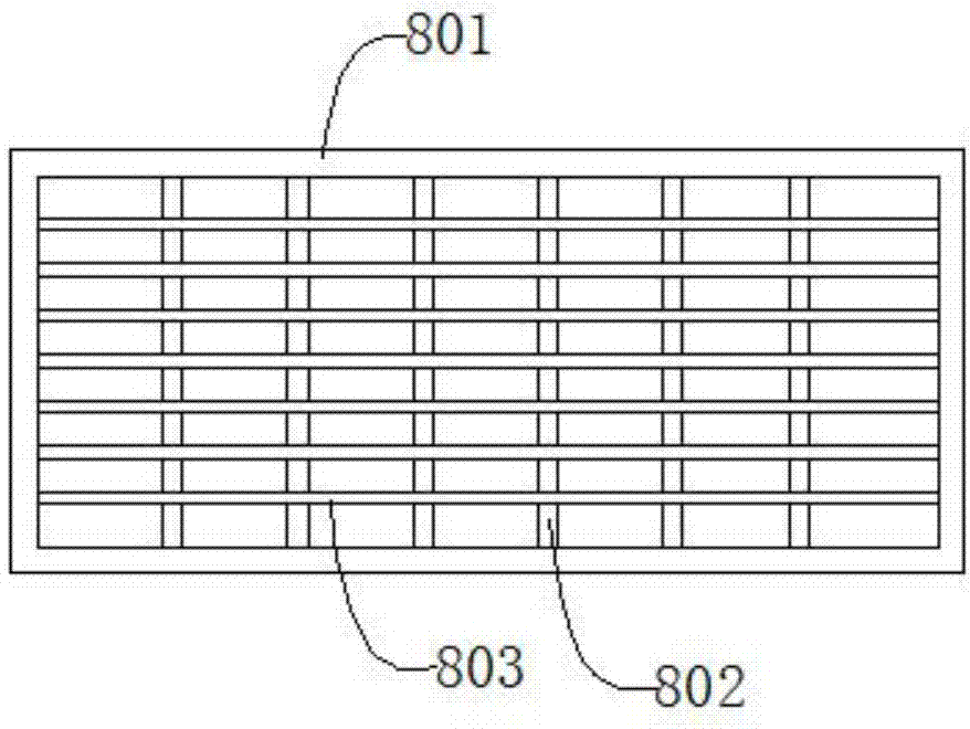
[0037] Such as figure 1 , figure 2 , image 3 , Figure 4 , Figure 5 , Figure 6As shown, a sludge pretreatment device includes a support plate 1, a bracket 2, a feeding nozzle 3, an upper feeding bin 4, a motor 5, an impeller 6, a feeding nozzle 7, a lower grid 8, a guide rod 9, an upper Grille 10, swing mechanism 11, connecting plate 12, limit plate 13, steel ball 14, described support 2 is positioned at the upper end of support plate 1, and described support 2 is connected with support plate 1 threadedly, and described feeding nozzle 3 is located at the lower end of the support plate 1, the feeding nozzle 3 is threadedly connected with the support plate 1, the upper material bin 4 is located at the upper end of the bracket 2, the upper material bin 4 is threadedly connected with the bracket 2, and the motor 5 is located at the upper end of the upper feed bin 4, the motor 5 is screwed to the upper feed bin 4, the impeller 6 is located at the lower end of the motor 5 a...


PUM


Abstract

The invention discloses a sludge pretreatment device which comprises a support plate, a support, a discharge nozzle, a loading bin, a motor, an impeller, a keep-off nozzle, a lower grid, guide rods, an upper grid, a swinging mechanism, a connecting plate, a spacing plate and a steel ball. The swinging mechanism further comprises a bracket, a power mechanism, rotating shafts, cams, sliding plates, guide wheels and a reset mechanism; the reset mechanism further comprises a push top, a spacing rod, and a spring. The sludge pretreatment device is simple in structure, sludge is continuously pressed into the upper grid through the impeller, the swinging mechanism pushes the upper grid to move reciprocatingly, the sludge is crushed horizontally and longitudinally under the common action of the upper grid and the lower grid, the sludge can be sliced evenly, continuously and rapidly, the sludge is allowed to fall into the discharge nozzle rapidly through continuous conveying of the impeller, and high efficiency is achieved.

Description

technical field [0001] The invention relates to a mechanical device, in particular to a sludge pretreatment device. Background technique [0002] In the existing sludge treatment technologies of urban sewage treatment plants, most of them use pressure filtration or natural drying, and the water content is very high. The treated sludge can only be temporarily solidified, and as landfill treatment, it can only be a temporary treatment plan. Can not meet the increasingly stringent environmental requirements. Therefore, sludge drying technology has emerged, that is, through heating and drying, the water content of sludge is lower than 10%, and then recycled. The sludge drying process mainly includes sludge collection, continuous feeding, drying, dehydration and For comprehensive utilization, when feeding continuously, because the sludge may contain agglomerated large pieces of sludge, if it is directly dried, it will often not be completely dried and dehydrated, which will affe...

Claims


Application Information

Patent Timeline
Patent Type & Authority Applications(China)
IPC IPC(8): C02F11/12
CPCC02F11/12
Inventor 王效平
Owner 东至县文元瓷砖加工厂
Why Eureka
Try Eureka