
Flying wing layout stealth unmanned aerial vehicle power system

A technology of maneuvering and unmanned aerial vehicles, which is applied in the directions of power units, aircraft parts, and jet power units on aircraft, can solve problems such as poor stealth effect, and achieve the goal of reducing infrared characteristics, improving stealth effect, and reducing infrared characteristics. Effect

Pending Publication Date: 2017-11-24
西安天拓航空科技有限公司
View PDF8 Cites 8 Cited by
  • Summary
  • Abstract
  • Description
  • Claims
  • Application Information

AI Technical Summary

Problems solved by technology

[0003] The purpose of the present invention is to overcome the deficiency of poor stealth effect of the existing UAV power system, and provide a stealth UAV power system with good stealth effect

Method used


Image

  • Flying wing layout stealth unmanned aerial vehicle power system
  • Flying wing layout stealth unmanned aerial vehicle power system
  • Flying wing layout stealth unmanned aerial vehicle power system

Examples


Embodiment Construction

[0037] The present invention will be described in further detail below in conjunction with the accompanying drawings and embodiments.

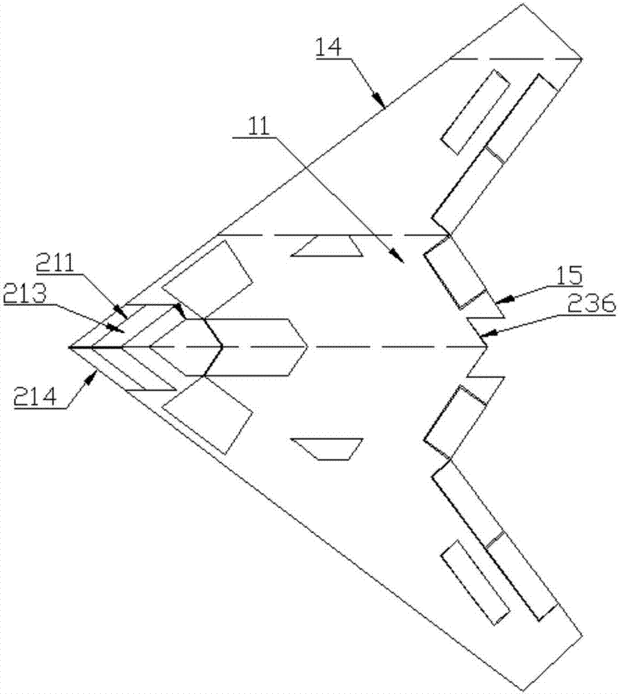
[0038] The power system adopted in the present invention is used for a stealth drone with a flying wing layout, and the stealth drone with a flying wing layout mainly includes a flying wing overall, a power system, a flight control system and a leading edge load system. The flying wing generally includes a left wing section, a right wing section arranged symmetrically with the left wing section; Section; The right wing section comprises the first right wing section 11, the second right wing section, and the right three wing section arranged sequentially from inside to outside.

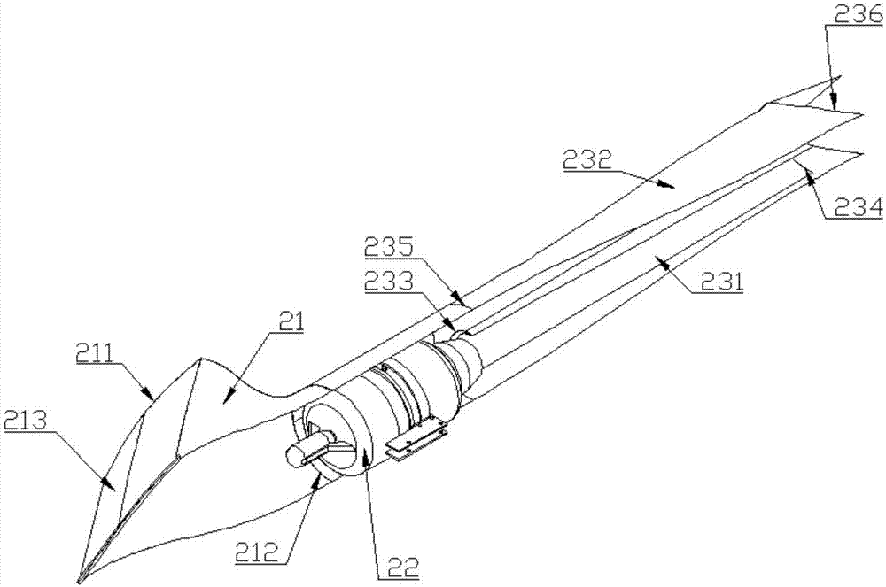
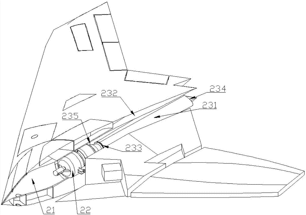
[0039] Such as figure 1 The power system of a stealth UAV with a flying wing layout shown includes an air intake 21, a turbojet engine 22 and an exhaust nozzle 23 connected in sequence from the nose to the tail.

[0040] The inlet cross-sectional area of ​​the air in...


PUM


Abstract

The invention relates to the technical field of unmanned aerial vehicles, aims to overcome the defect of the poor stealth effect of an existing unmanned aerial vehicle power system, and provides a stealth unmanned aerial vehicle power system good in stealth effect and small in thrust loss. The stealth unmanned aerial vehicle power system comprises an air inlet channel, a turbine jet engine and an exhaust nozzle which are sequentially connected from a handpiece to a tail. An air inlet of the air inlet channel is formed in a back, and the cross section of the air inlet is square. The lower edge of the air inlet coincides with the front edge of an unmanned aerial vehicle. The air inlet is provided with a radar shielding net made of a conducting material. The surface of the radar shielding net and the surface of the stealth unmanned aerial vehicle keep curvature continuity and are in electric breakover.

Description

technical field [0001] The invention relates to the technical field of unmanned aerial vehicles, in particular to a power system of a stealth unmanned aerial vehicle with flying wing layout. Background technique [0002] For general subsonic jet drones, for the purpose of saving space inside the fuselage, the engine is usually carried on the fuselage or hung on the two wings. However, the stealth effect of the external engine compartment is poor; and the engine in the form of suspension and piggyback arrangement has a large windward area, which will generate greater resistance, resulting in greater thrust loss. Contents of the invention [0003] The purpose of the present invention is to overcome the deficiency of poor stealth effect of the existing unmanned aerial vehicle power system, and provide a stealth unmanned aerial vehicle power system with good stealth effect. [0004] In order to achieve the above object, the technical solution provided by the present invention...

Claims


Application Information

Patent Timeline
Patent Type & Authority Applications(China)
IPC IPC(8): B64D27/20B64D33/02B64D33/04
CPCB64D27/20B64D33/02B64D33/06B64D2033/0273
Inventor 不公告发明人
Owner 西安天拓航空科技有限公司
Learn More