
Diamond abrasive disc based on spot welding and manufacture process thereof

A manufacturing process, diamond technology, applied in the direction of manufacturing tools, metal processing equipment, grinding devices, etc., can solve the problems of relatively large heat-affected zone, high production cost, performance impact, etc., to achieve easy control operation, avoid random sliding, The effect of easy operation

Pending Publication Date: 2017-11-24
福州市闽福石材磨具有限公司
View PDF8 Cites 2 Cited by
  • Summary
  • Abstract
  • Description
  • Claims
  • Application Information

AI Technical Summary

Problems solved by technology

[0002] At present, diamond grinding discs are widely used in the grinding and polishing of stone, floor materials and hard and brittle non-metallic materials. Diamond cutter heads and grinding discs are usually connected by welding methods, such as high-frequency heating welding and silver brazing. These welding methods are It will cause secondary heating of the diamond segment, and the temperature of this secondary heating is very close to the hot pressing temperature of the diamond segment, and its heat-affected zone is relatively large, so it will have a significant impact on its performance, and even greatly reduce the diamond segment. In addition, due to the consumption of a large amount of flux and silver electrodes during brazing, the production cost is relatively high, and the working environment of the production workers is relatively harsh, and they must be in the high temperature of brazing for a long time. Therefore, we propose a Diamond grinding disc based on spot welding and its manufacturing process

Method used


Image

  • Diamond abrasive disc based on spot welding and manufacture process thereof
  • Diamond abrasive disc based on spot welding and manufacture process thereof
  • Diamond abrasive disc based on spot welding and manufacture process thereof

Examples


Embodiment 1

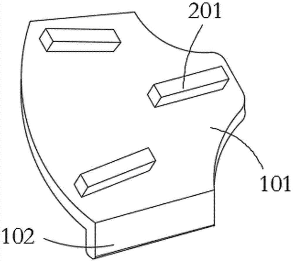
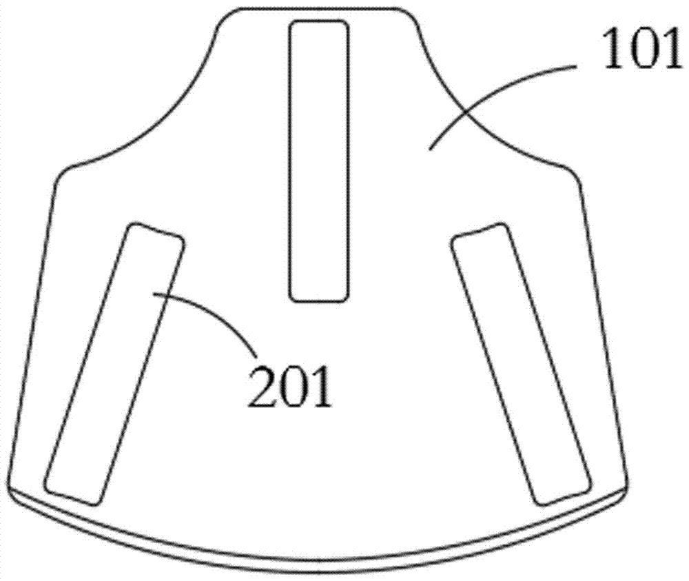
[0038] see Figure 1-8 , the present invention provides a technical solution: a diamond grinding disc based on spot welding, comprising an iron substrate 101, the top surface of the iron substrate 101 is welded with a cutter head assembly 201, and the cutter head assembly 201 is a cuboid structure, its There are three groups, which are evenly distributed on the top surface of the iron sheet substrate 101 .

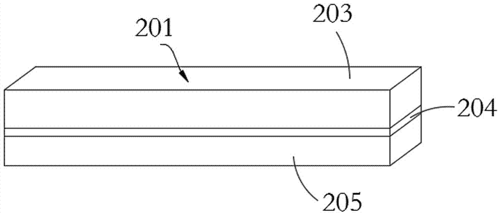
[0039] see Figure 1-5 , the cutter head assembly 201 comprises an iron bar 205, a connecting layer 204 and a cutter head 203, the iron bar 205 is fixed on the iron sheet substrate 101 by spot welding, the connecting layer 204 is positioned on the top surface of the iron bar 205, and the cutter head 203 is positioned at the connecting layer 204 Above, the cutter head 203 and the iron bar 205 in the cutter head assembly 201 can be firmly fused together by using the connecting layer 204 at a relatively low temperature.

[0040] The connection layer 204 here can also be an ...

Embodiment 2

[0057] see Figure 1-8 , the present invention provides a technical solution: a diamond grinding disc based on spot welding, comprising an iron substrate 101, the top surface of the iron substrate 101 is welded with a cutter head assembly 201, and the cutter head assembly 201 is a cuboid structure, its There are three groups, which are evenly distributed on the top surface of the iron sheet substrate 101 .

[0058] see Figure 1-5 , the cutter head assembly 201 comprises an iron bar 205, a connecting layer 204 and a cutter head 203, the iron bar 205 is fixed on the iron sheet substrate 101 by spot welding, the connecting layer 204 is positioned on the top surface of the iron bar 205, and the cutter head 203 is positioned at the connecting layer 204 Above, the cutter head 203 and the iron bar 205 in the cutter head assembly 201 can be firmly fused together by using the connecting layer 204 at a relatively low temperature.

[0059] The connection layer 204 here can also be an ...

Embodiment 3

[0076] see Figure 1-8 , the present invention provides a technical solution: a diamond grinding disc based on spot welding, comprising an iron substrate 101, the top surface of the iron substrate 101 is welded with a cutter head assembly 201, and the cutter head assembly 201 is a cuboid structure, its There are three groups, which are evenly distributed on the top surface of the iron sheet substrate 101 .

[0077] see Figure 1-5 , the cutter head assembly 201 comprises an iron bar 205, a connecting layer 204 and a cutter head 203, the iron bar 205 is fixed on the iron sheet substrate 101 by spot welding, the connecting layer 204 is positioned on the top surface of the iron bar 205, and the cutter head 203 is positioned at the connecting layer 204 Above, the cutter head 203 and the iron bar 205 in the cutter head assembly 201 can be firmly fused together by using the connecting layer 204 at a relatively low temperature.

[0078] The connection layer 204 here can also be an ...


PUM

PropertyMeasurementUnit
thicknessaaaaaaaaaa
thicknessaaaaaaaaaa
thicknessaaaaaaaaaa

Abstract

The invention provides a diamond abrasive disc based on spot welding. The diamond abrasive disc comprises an iron sheet substrate, and a cutter head component is arranged welded on the top surface of the iron sheet substrate. The cutter head component comprises an iron bar, a connecting layer and a cutter head, and the iron bar is fixed to the iron sheet substrate through spot welding. The connecting layer is positioned on the top surface of the iron bar, and the cutter head is positioned above the connecting layer. Welding spots are arranged on the bottom surface of the iron sheet substrate. The invention also provides a manufacture process of the diamond abrasive disc based on spot welding. The manufacture process comprises the steps of placing the cutter head, sprinkling into alloyed powder, placing the iron bar, hot pressing, setting the welding spots, welding and cooling. As the connecting layer can pass through relatively low temperature, the cutter head and the iron bar in the cutter head component can be firmly fused together. The iron sheet substrate and the cutter head component are dotted through spot welding to be fused together. The sprinkling amount of the alloyed powder can be regulated by controlling the speed of a motor.

Description

technical field [0001] The invention relates to the technical field of grinding discs, in particular to a diamond grinding disc based on spot welding and a manufacturing process thereof. Background technique [0002] At present, diamond grinding discs are widely used in the grinding and polishing of stone, floor materials and hard and brittle non-metallic materials. Diamond cutter heads and grinding discs are usually connected by welding methods, such as high-frequency heating welding and silver brazing. These welding methods are It will cause secondary heating of the diamond segment, and the temperature of this secondary heating is very close to the hot pressing temperature of the diamond segment, and its heat-affected zone is relatively large, so it will have a significant impact on its performance, and even greatly reduce the diamond segment. In addition, due to the consumption of a large amount of flux and silver electrodes during brazing, the production cost is relative...

Claims


Application Information

Patent Timeline
Patent Type & Authority Applications(China)
IPC IPC(8): B24D18/00B23K31/02
CPCB23K31/02B24D18/0009
Inventor 陈贤河
Owner 福州市闽福石材磨具有限公司
Learn More