
Clamping mechanism for automatic glass edger

A technology of clamping mechanism and edging machine, which is applied in the direction of machine tools suitable for grinding the edge of workpieces, parts of grinding machine tools, grinding machines, etc., and can solve the problem that the clamping force cannot be too large, the glass is loose or shifted, and the grinding is affected Quality and other issues to achieve the effect of preventing loosening or shifting, preventing glass damage, and high degree of automation

Inactive Publication Date: 2017-11-24
ANHUI UNIVERSITY OF TECHNOLOGY AND SCIENCE
View PDF6 Cites 13 Cited by
  • Summary
  • Abstract
  • Description
  • Claims
  • Application Information

AI Technical Summary

Problems solved by technology

[0003] However, the clamping mechanism of the existing automatic glass edging machine has the following defects. One is that when the clamping mechanism clamps the glass and grinds the four sides of the glass one by one, the rotation operation of the glass is complicated and the degree of automation is not high. The efficiency of grinding is not conducive to large-scale production; the second is that the material of the glass determines that the clamping force cannot be too large, otherwise the glass is easily damaged, but the clamping force of the clamping mechanism is too small to make the clamping of the glass unstable, making the glass easy to Looseness or deviation will affect the quality of grinding. In order to solve these problems, a clamping mechanism for automatic glass edge grinding machine is designed.

Method used


Image

  • Clamping mechanism for automatic glass edger

Examples


Embodiment

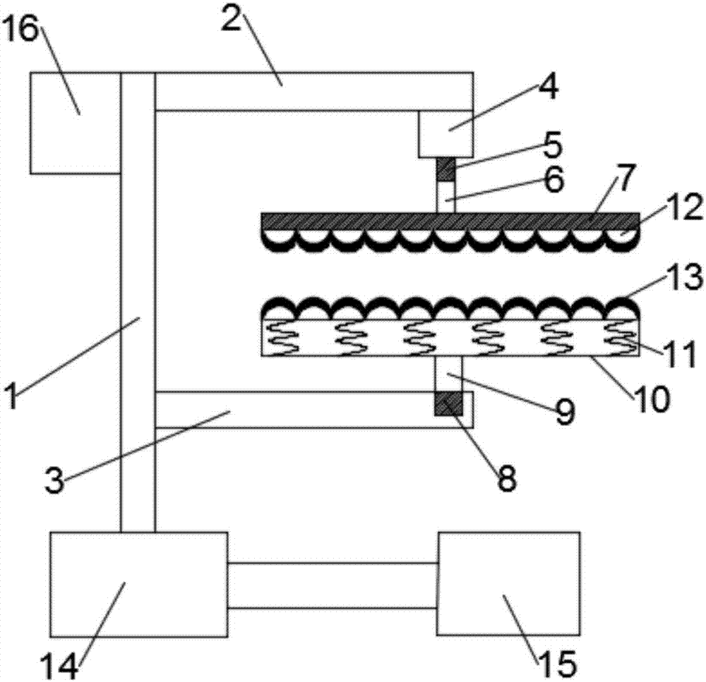
[0021] Such as figure 1 As shown, the present invention provides a clamping mechanism for an automatic glass edging machine, including a bracket 1, the bottom end of the bracket 1 is fixedly connected with a mobile base 14, and the side of the mobile base 14 is provided with a cylinder 15, so that The cylinder 15 is fixed, and the output end of the cylinder 15 is fixedly connected to the mobile base 14, so that the mobile base 14 can reciprocate under the drive of the cylinder 15, which is convenient for glass edging. The side of the support 1 is fixedly connected with a horizontal setting The first support rod 2 and the second support rod 3, and the first support rod 2 is located directly above the second support rod 3, the side top of the bracket 1 is fixedly connected with a counterweight 16, and the counterweight 16 is located The opposite positions of the first support rod 2 and the second support rod 3 can prevent the clamping mechanism from tilting and prevent deviation...


PUM


Abstract

The invention discloses a clamping mechanism for an automatic glass edging machine, which includes a bracket. The side of the bracket is fixedly connected with a first support rod and a second support rod. The first support rod is located directly above the second support rod. The other end of the support rod is connected with a stepper motor, the stepper motor includes an output shaft, the output shaft is vertically arranged downwards, the bottom end of the output shaft is connected with a telescopic rod, the bottom end of the telescopic rod is connected with a first clamping plate, and the bottom end of the telescopic rod is connected with a first clamping plate. The other end of the two support rods is provided with a rotating groove, and a rotating shaft is installed in the rotating groove, and the other end of the rotating shaft extends out of the rotating groove, and the top of the rotating shaft is connected with a second clamping plate, and the second clamping plate is Double-layer hollow structure, the inside of the second clamping plate is equipped with several shock-absorbing springs, this device can realize the rotation of the glass during edging easier and with a higher degree of automation, and at the same time make the clamping of the glass more stable, so that the glass does not There will be looseness or offset, which improves the quality of glass edging and is worth promoting.

Description

technical field [0001] The invention relates to the field of automatic mechanical equipment, in particular to a clamping mechanism for an automatic glass edger. Background technique [0002] Glass edging machine is one of the earliest and most widely used mechanical equipment in glass deep processing equipment. Its main function is to smooth the glass and make some special shapes. The correct and reasonable use of the edging machine can not only ensure the normal production, but also prolong the life of the machine. Glass edging machine is divided into single-arm special-shaped edging machine, linear edging machine, and profiling edging machine. In modern glass production, glass edging machines are usually controlled automatically, and the clamping mechanism of automatic glass edging machines is crucial to glass production and glass quality. [0003] However, the clamping mechanism of the existing automatic glass edging machine has the following defects. One is that when t...

Claims


Application Information

Patent Timeline
Patent Type & Authority Applications(China)
IPC IPC(8): B24B41/06B24B47/20B24B9/10
CPCB24B41/06B24B9/10B24B47/20
Inventor 王军杨洋
Owner ANHUI UNIVERSITY OF TECHNOLOGY AND SCIENCE
Learn More